1. Product Overview
The waveshare USB to UART/I2C/SPI/JTAG Converter is a versatile tool designed for developers and enthusiasts working with various communication protocols. It supports conversion from USB to 2-channel UART, or USB to 1-channel UART + 1-channel I2C + 1-channel SPI, or USB to 1-channel UART + 1-channel JTAG. This device offers high-speed communication, flexible voltage selection, and robust protection features, making it suitable for a wide range of embedded system development and debugging tasks.
Key Features:
- Multi-Interface Support: Supports USB to 2-ch UART, or USB to 1-ch UART + 1-ch I2C + 1-ch SPI, or USB to 1-ch UART + 1-ch JTAG.
- High-Speed UART: Features 2-channel high-speed UART interfaces with up to 9Mbps baud rate, including CTS and RTS hardware automatic flow control.
- I2C Interface: 1-channel I2C interface for easy operation of EEPROM or programming I2C devices like OLEDs and sensors.
- SPI Interface: 1-channel SPI interface with two chip select signal pins, allowing control of two SPI slave devices simultaneously.
- JTAG Interface: 1-channel JTAG interface, compatible with OpenOCD for debugging and testing (user evaluation recommended).
- Flexible Operating Level: Onboard 3.3V and 5V level conversion circuit for switching communication interface operating levels, ensuring broad compatibility.
- Robust Protection: Integrated resettable fuse and ESD protection circuit to prevent over-current and over-voltage, ensuring safe and stable communication.
- Durable Design: Encased in an aluminum alloy with an oxidation dull-polish surface and CNC process opening, providing a solid and durable build.
- High-Quality Connectors: Equipped with high-quality USB-B and DC connectors for smooth plug & pull, durability, and anti-reverse protection.
2. Package Content
The package for the waveshare USB to UART/I2C/SPI/JTAG Converter typically includes the following items:
- waveshare USB to UART/I2C/SPI/JTAG Converter unit
- USB-B cable
- Assorted jumper wires for connections
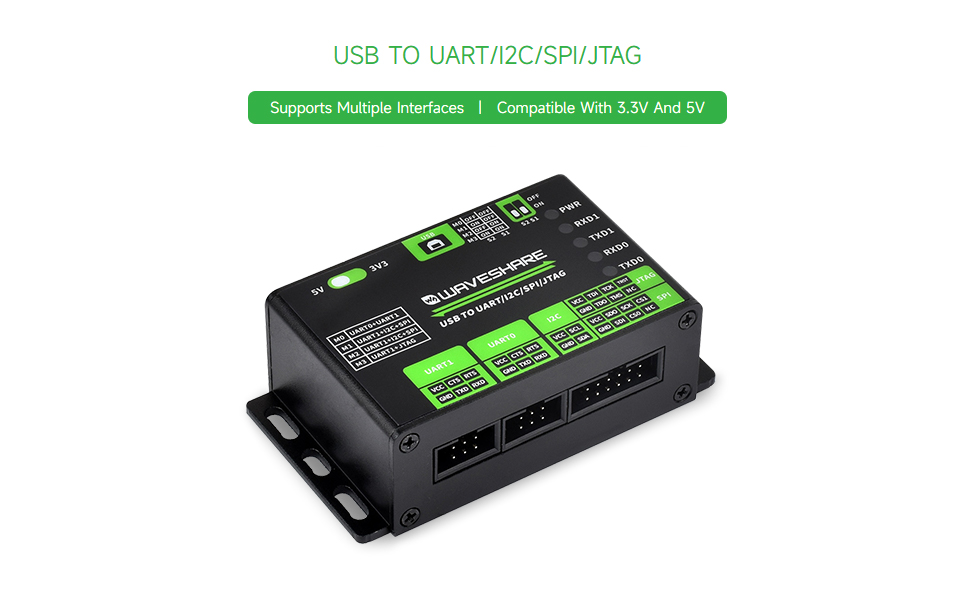
Figure 2.1: Contents of the waveshare USB to UART/I2C/SPI/JTAG Converter package, showing the main unit, USB cable, and jumper wires.
3. Setup
Follow these steps to set up your waveshare USB to UART/I2C/SPI/JTAG Converter:
3.1 Driver Installation
Before connecting the device, ensure the necessary drivers are installed on your operating system. Drivers are typically available for Windows and Linux. Refer to the official waveshare product page or included documentation for specific driver download and installation instructions.

Figure 3.1: Example of driver installation guides for Windows and Linux operating systems, showing command line instructions and device manager views.
3.2 Hardware Connection
- Connect to PC: Use the provided USB-B cable to connect the converter to a USB port on your computer. The PWR indicator LED should light up, indicating power.
- Select Operating Voltage: Use the onboard toggle switch (labeled 5V/3V3) to select the appropriate operating voltage (3.3V or 5V) for your target device. Ensure this matches the voltage requirements of the device you are connecting to prevent damage.
- Select Operating Mode: Configure the DIP switches (S1, S2) on the back of the device to select the desired communication mode. Refer to the table below for mode configurations:
Table 3.1: Operating Mode Selection Mode (M0-M3) S2 S1 Function M0 OFF OFF UART0 + UART1 M1 OFF ON UART1 + I2C + SPI M2 ON OFF UART1 + I2C + SPI M3 ON ON UART1 + JTAG - Connect Target Device: Use the appropriate jumper wires to connect the converter's interface pins (UART0, UART1, I2C, SPI, JTAG) to your target device according to the selected mode. Pay close attention to pin assignments (VCC, GND, TXD, RXD, SCL, SDA, SCK, MISO, MOSI, CS, TDI, TDO, TCK, TMS, TRST).

Figure 3.2: The converter connected to a target device via jumper wires, illustrating a typical setup for communication.

Figure 3.3: Detailed view of the converter's interface and mode description, including indicator lights and DIP switch settings.
4. Operating Instructions
Once the hardware is connected and drivers are installed, you can begin using the converter for communication with your target device.
4.1 Indicator Lights
The converter features several indicator lights to provide feedback on its status:
- PWR: Power indicator, lights up when the USB is connected and voltage is detected.
- RXD1: UART1 receiving indicator, lights up when the device sends data back.
- TXD1: UART1 sending indicator, lights up when the USB port sends data.
- RXD0: UART0 receiving indicator, lights up when the device sends data back.
- TXD0: UART0 sending indicator, lights up when the USB port sends data.
4.2 Using UART Interfaces
In M0 mode (UART0 + UART1), both UART channels are active. Use a serial terminal program on your computer to communicate. Configure the baud rate, data bits, parity, and stop bits to match your target device. The converter supports baud rates up to 9Mbps with hardware flow control (CTS/RTS).
4.3 Using I2C and SPI Interfaces
In M1 or M2 mode (UART1 + I2C + SPI), you can utilize the I2C and SPI interfaces. Dedicated software tools or custom scripts are typically used to interact with I2C EEPROMs, OLEDs, sensors, or SPI slave devices. The SPI interface provides two chip select pins (CS0, CS1) for controlling multiple slave devices.
4.4 Using JTAG Interface
In M3 mode (UART1 + JTAG), the JTAG interface is enabled. This is primarily used for debugging and testing microcontrollers or FPGAs. Tools like OpenOCD can be used in conjunction with the JTAG interface. Users should verify compatibility and functionality with their specific JTAG debugging setup.
Video 4.1: An official waveshare video demonstrating the features and usage of the USB to UART/I2C/SPI/JTAG converter, highlighting its multi-interface capabilities and application in IoT development.
5. Specifications
Below are the detailed technical specifications for the waveshare USB to UART/I2C/SPI/JTAG Converter:
| Feature | Description |
|---|---|
| Host Interface | USB |
| Power Supply | USB port, 5V |
| Operating Level | 3.3V/5V (selectable via onboard switch) |
| USB Connector | USB-B |
| Interface Protection | Resettable fuse, ESD protection |
| UART Channels | 2 (M0 mode: UART0 + UART1) |
| UART Connector | 6PIN IDC connector |
| UART Baud Rate | 1200bps ~ 9Mbps |
| UART Flow Control | CTS and RTS |
| I2C Channel | 1 (M1/M2 mode) |
| I2C Connector | 12PIN IDC connector (first 4 pins are I2C) |
| SPI Channel | 1 (M1/M2 mode) |
| SPI Connector | 12PIN IDC connector (last 8 pins are SPI) |
| JTAG Channel | 1 (M3 mode) |
| JTAG Connector | 12PIN IDC connector (last 8 pins are JTAG) |
| Dimensions | 86.0 × 48.0 × 27.6mm |
| Item Weight | 5.6 ounces |
| Manufacturer | Waveshare |

Figure 5.1: Technical drawing showing the outline dimensions of the converter in millimeters.
6. Maintenance
Proper maintenance ensures the longevity and reliable operation of your waveshare converter:
- Keep Dry: Avoid exposing the device to moisture or liquids, as this can cause short circuits and damage.
- Clean Gently: Use a soft, dry cloth to clean the exterior of the device. Do not use harsh chemicals or abrasive materials.
- Handle with Care: While durable, avoid dropping the device or subjecting it to strong impacts.
- Storage: Store the converter in a cool, dry place away from direct sunlight and extreme temperatures when not in use.
- Cable Management: Ensure USB and jumper cables are not excessively bent or strained to prevent internal wire damage.
7. Troubleshooting
If you encounter issues with your waveshare converter, refer to the following troubleshooting tips:
- No Power (PWR LED off):
- Ensure the USB cable is securely connected to both the converter and the computer.
- Try a different USB port or USB cable.
- Verify your computer's USB port is functional.
- Communication Failure:
- Driver Issues: Reinstall the latest drivers from the waveshare website. For Linux, ensure kernel modules are correctly loaded and user-space software is properly configured. Some users have reported challenges with Linux driver support and Python sample code; consult community forums or waveshare support for updated resources.
- Incorrect Mode Selection: Double-check the DIP switch settings (S1, S2) to ensure the correct operating mode (M0-M3) is selected for your application.
- Incorrect Voltage Level: Verify the 3.3V/5V toggle switch is set to match your target device's voltage.
- Incorrect Wiring: Carefully review your connections between the converter and the target device. Ensure VCC, GND, TXD, RXD, and other protocol-specific pins are correctly matched.
- Baud Rate Mismatch (UART): Confirm that the baud rate in your serial terminal software matches the baud rate of your target device.
- Indicator Lights: Observe the RXD/TXD indicator lights. If they are not blinking during data transmission, it indicates a lack of communication.
- Device Not Recognized by OS:
- Check Device Manager (Windows) or `lsusb`/`dmesg` (Linux) to see if the device is detected.
- Ensure drivers are correctly installed and the device is not showing any errors.
8. Warranty and Support
For warranty information, technical support, and additional resources, please visit the official waveshare website. You can find detailed documentation, driver downloads, and contact information for customer service there.
While the product is from waveshare, some related products from DSD TECH offer at least 12 months of warranty and lifetime technical support. Please refer to the specific product's warranty details provided by waveshare for accurate information regarding this converter.
For further assistance, you may also refer to the waveshare Amazon Store.