Introduction
This manual provides detailed instructions for the installation, operation, and troubleshooting of your GOWENIC 5V 3-Pin ARGB Controller. This device is designed to provide manual control over 5V 3-pin Addressable RGB (ARGB) lighting products, such as case fans, LED strips, and cooling radiators, without requiring a motherboard with ARGB headers.
Product Overview
The GOWENIC ARGB Controller offers a user-friendly solution for managing your system's lighting. Its compact design and intuitive buttons allow for easy adjustments to lighting modes, speeds, and colors.
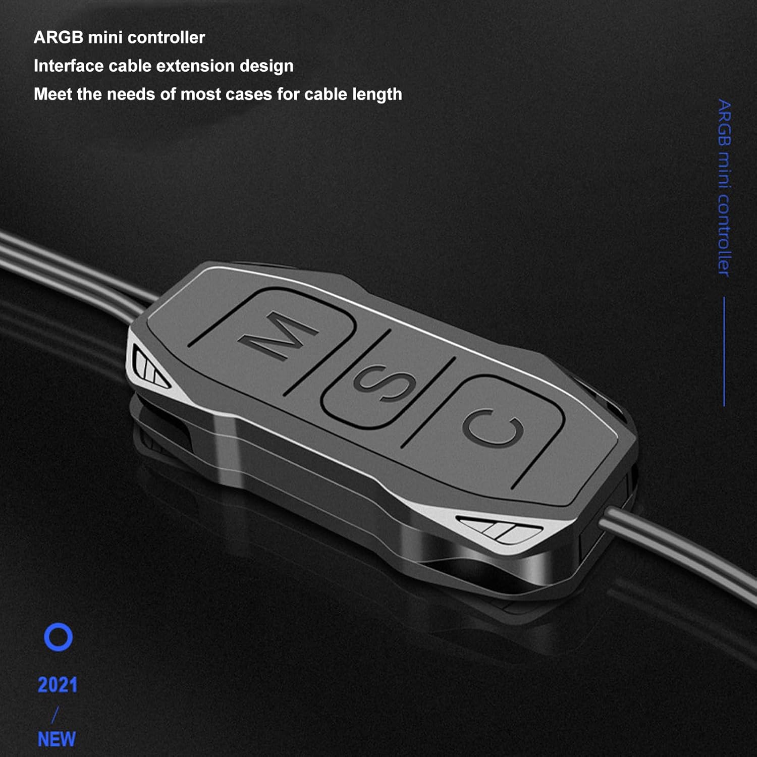
Figure 1: GOWENIC ARGB Mini Controller. This image shows the compact design of the controller, highlighting its interface cable extension for flexible placement within a PC case.
- Convenient Design: Features 'M', 'S', and 'C' buttons for effortless switching of lighting modes, speeds, and colors.
- Simple Manual Controls: Allows easy switching between various lighting effects without the need for motherboard ARGB header support.
- Multiple Lighting Modes: Provides easy control of 5V 3-pin ARGB products with a variety of built-in lighting modes.
- Effortless Installation: Includes an interface cable extension for easy connections, ensuring optimal cable length for different setups.
- Versatile ARGB Compatibility: Compatible with various 5V ARGB devices such as case fans, lamps, and cooling radiators for customizable lighting options.

Figure 2: Wide Compatibility. This image illustrates the standard 5V ARGB interface, emphasizing compatibility with a broad range of 5V 3-pin ARGB light-emitting products.
Specifications
| Item Type | ARGB Controller |
| Material | ABS |
| Scope of Application | 5V 3-pin RGB Light Bar and other 5V ARGB devices |
| Package Dimensions | 6.18 x 4.25 x 0.35 inches |
| Item Weight | 0.704 ounces |
| Model Number | GOWENICxr2vchu0g5 |
| Interface Cable Length | Approx. 160 ± 10mm / 6.3 ± 0.39in |
| Power Supply Line Length | Approx. 500 ± 10mm / 19.7 ± 0.39in |
Installation
Follow these steps to properly install your GOWENIC ARGB Controller:
- Connect ARGB Devices: Connect your 5V 3-pin ARGB devices (e.g., light bars, fans) to the 5V 3-pin male connector on the ARGB controller. Ensure the arrow on the connector aligns with the 5V pin on your ARGB device.
- Connect Power: Connect the SATA interface male connector from the ARGB controller to a female SATA power connector from your computer's power supply.
- Secure Placement: Position the controller in a suitable location within your PC case, ensuring cables are routed neatly and do not obstruct airflow. The extended cable lengths provide flexibility for various setups.

Figure 3: Installation Diagram. This diagram illustrates the connection flow from a 5V ARGB light bar to the controller, and then from the controller to the computer's power supply via a SATA interface.

Figure 4: Cable Lengths. This image displays the controller with its interface cable (approx. 160mm) and power supply line (approx. 500mm), designed for easy and flexible connection.
Video 1: ARGB Controller Connection Guide. This video demonstrates the physical connection process for the ARGB controller, showing how to connect it to ARGB devices and the power supply.
Operation
The GOWENIC ARGB Controller features three buttons for easy control of your lighting effects:
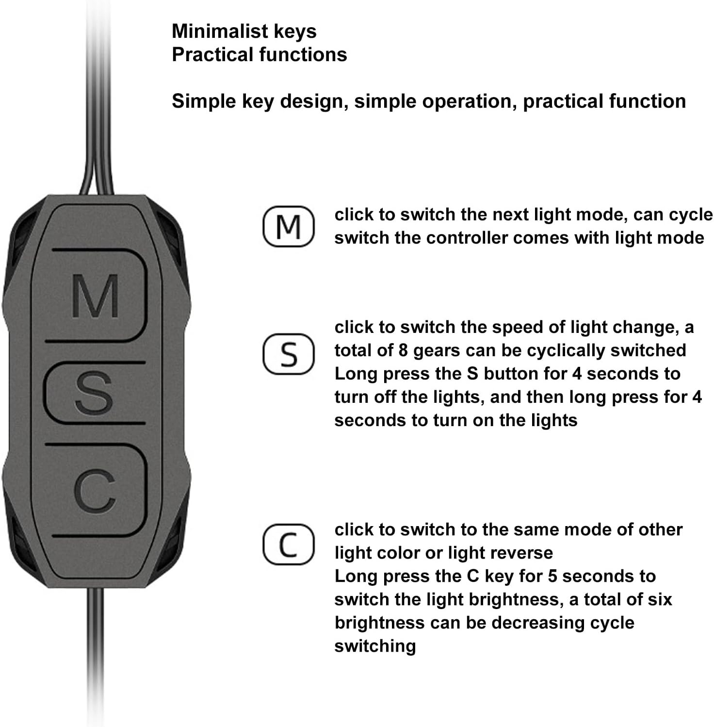
Figure 5: Controller Button Functions. This image provides a detailed explanation of each button's function on the ARGB controller.
- M Button (Mode):
- Short Press: Cycles through the next available lighting mode. The controller comes with various built-in lighting modes.
- S Button (Speed/On/Off):
- Short Press: Cycles through 8 different light change speeds.
- Long Press (4 seconds): Turns off the lights.
- Long Press (4 seconds again): Turns on the lights.
- C Button (Color/Brightness):
- Short Press: Switches to the next light color or reverses the light direction within the current mode.
- Long Press (5 seconds): Cycles through six levels of light brightness (decreasing cycle).
Troubleshooting
If you encounter issues with your GOWENIC ARGB Controller, please refer to the following common problems and solutions:
- Lights Not Turning On:
- Ensure the SATA power connector is securely connected to your computer's power supply.
- Verify that the 5V 3-pin ARGB devices are correctly connected to the controller, paying attention to pin alignment.
- Try a long press (4 seconds) on the 'S' button to ensure the lights are not simply turned off.
- Lights Not Changing Modes/Colors/Speed:
- Confirm that the 'M', 'S', and 'C' buttons are being pressed correctly as described in the Operation section.
- Check all connections for looseness or incorrect orientation.
- If the controller becomes unresponsive, disconnect power for a few seconds and then reconnect to perform a soft reset.
- Lights Stuck on One Color (e.g., Dark Blue):
- This can sometimes indicate an internal issue with the controller or a connected ARGB device. Try disconnecting all ARGB devices from the controller and testing them individually if possible.
- Perform a power cycle (disconnect and reconnect power) to the controller.
- If the issue persists, consider contacting customer support.
Package Contents
The package includes the following items:
- 1 x GOWENIC ARGB Controller

Figure 6: Package Contents. This image shows the complete GOWENIC ARGB Controller unit with its attached cables.
Warranty and Support
For warranty information or technical support, please refer to the retailer's policy or contact GOWENIC customer service through their official channels. Keep your purchase receipt for warranty claims.