1. Introduction
The HUIOP NJTY T5 is a compact, intelligent, and reliable True RMS digital multimeter designed for accurate measurements in various electrical applications. Featuring a large 3.8-inch LCD display with 6000 counts and a backlight, it provides clear and precise readings. This device intelligently recognizes and measures AC/DC voltage, AC/DC current, resistance, frequency, and continuity, automatically switching to the appropriate range. It also supports manual selection for diode, capacitance, and temperature measurements.
Its portable size, similar to a smartphone, makes it convenient for transport, and the included transparent case protects it from scratches and drops. Equipped with dual flashlights, it assists in illuminating work areas in low-light conditions. Constructed from durable ABS material, the T5 multimeter meets IEC61010 safety standards for 600V CAT II and pollution grade 2, ensuring reliable performance for both professionals and general users.
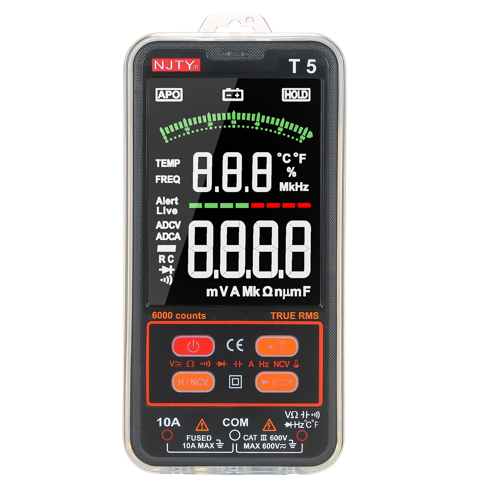
Figure 1: HUIOP NJTY T5 Digital Multimeter with test leads. A clear view of the HUIOP NJTY T5 Digital Multimeter, featuring its large display and connected test leads, ready for use.
2. Safety Information
To ensure safe operation and avoid damage to the meter, please read this manual carefully before use. Observe all warnings and precautions. This device complies with IEC 61010-1 safety standards for 600V CAT II and pollution grade 2.
- Do not exceed the maximum input values specified for each measurement range.
- Exercise extreme caution when working with voltages above 30V AC RMS, 42V peak, or 60V DC. These voltages pose a shock hazard.
- Always disconnect the test leads from the circuit before changing functions or ranges.
- Ensure the test leads are properly seated in the correct input jacks for the desired measurement.
- Replace batteries immediately when the low battery indicator appears to ensure accurate readings.
- Do not operate the meter if it appears damaged or if the battery cover is not properly closed.
- Do not use the meter in explosive gas, vapor, or dusty environments.
- Always use the correct fuse for replacement. Refer to the maintenance section for fuse specifications.
3. Package Contents
Verify that all items listed below are present and undamaged. If any item is missing or damaged, contact your vendor immediately.
- HUIOP NJTY T5 Digital Multimeter
- Pair of Test Leads (Red and Black)
- K-Type Thermocouple
- Zippered Carrying Pouch
- User Manual (English)

Figure 2: Package Contents. The complete package contents are laid out, showing the multimeter, a pair of test leads, a K-type thermocouple for temperature measurement, a zippered carrying pouch, and the user manual.
4. Product Overview
Familiarize yourself with the components and controls of your HUIOP NJTY T5 Digital Multimeter.

Figure 3: Multimeter Components. A detailed diagram of the multimeter with labels pointing to key features such as the LCD Display, Power Button, Data Hold, NCV Sensing Area, Input Sockets, and Function Buttons.
- Hanging Hole
- NCV Sensing Area
- Buzzer & NCV Indicator
- LCD Display
- Power Button
- Backlight & Flashlight Button
- Data Hold and NCV Button
- Diode/Capacitance/Temperature Switch Button
- 10A Input Socket (for current measurements up to 10A)
- COM Input Socket (common negative input for all measurements)
- V/Ω Input Socket (for voltage, resistance, capacitance, frequency, diode, continuity, and temperature measurements)
5. Setup
5.1 Battery Installation
The multimeter requires two 1.5V AAA batteries (not included) for operation. Follow these steps to install them:
- Ensure the multimeter is powered off and disconnect any test leads.
- Locate the battery compartment on the back of the meter.
- Use a screwdriver to loosen the screw securing the battery cover.
- Remove the battery cover.
- Insert two 1.5V AAA batteries, observing the correct polarity (+ and -) as indicated inside the compartment.
- Replace the battery cover and tighten the screw.

Figure 4: Battery Compartment. The rear cover of the multimeter is removed, revealing the battery compartment designed for two 1.5V AAA batteries and the internal fuse.
5.2 Connecting Test Leads
Always connect the black test lead to the COM (Common) input jack. Connect the red test lead to the appropriate input jack based on the measurement you intend to perform:
- For Voltage, Resistance, Capacitance, Frequency, Diode, Continuity, and Temperature measurements: Connect the red test lead to the V/Ω input jack.
- For Current measurements (up to 10A): Connect the red test lead to the 10A input jack.
Ensure the test leads are fully inserted into the jacks before taking any measurements.

Figure 5: Test Leads Connection. The multimeter is shown with its red and black test leads plugged into the input jacks, ready for measurement.
6. Operating Instructions
6.1 Power On/Off
- To power on the multimeter, press the Power Button (
 ).
). - To power off, press and hold the Power Button until the display turns off. The meter also features an auto power-off function after 10 minutes of inactivity.
6.2 Automatic and Manual Function Selection
The HUIOP NJTY T5 multimeter intelligently identifies and measures AC/DC voltage, AC/DC current, resistance, frequency, and continuity in its default auto mode. For other functions like Diode, Capacitance, and Temperature, manual selection is required.
- In auto mode, the meter will automatically detect the type of measurement (Voltage, Current, Resistance, Frequency, Continuity) and display the reading.
- To manually select Diode, Capacitance, or Temperature, press the Diode/Capacitance/Temperature Switch Button () to cycle through these functions.
Figure 6: Displayed Measurement Functions. HUIOP NJTY T5 Digital Multimeter display highlighting various measurement functions like voltage, current, resistance, frequency, and continuity.
6.3 Measuring Voltage (AC/DC)
- Connect the black test lead to the COM jack and the red test lead to the V/Ω jack.
- Power on the meter. It will automatically enter voltage measurement mode.
- Touch the test probes to the circuit points where you want to measure voltage. The display will show the voltage value and automatically detect if it's AC or DC.
6.4 Measuring Current (AC/DC)
- IMPORTANT: Ensure the circuit is de-energized before connecting the meter in series.
- Connect the black test lead to the COM jack and the red test lead to the 10A jack.
- Power on the meter. It will automatically enter current measurement mode.
- Open the circuit where you want to measure current and connect the meter in series.
- Re-energize the circuit. The display will show the current value and automatically detect if it's AC or DC.
- After measurement, de-energize the circuit before disconnecting the meter.
6.5 Measuring Resistance
- IMPORTANT: Ensure the circuit is de-energized and all capacitors are discharged before measuring resistance.
- Connect the black test lead to the COM jack and the red test lead to the V/Ω jack.
- Power on the meter. It will automatically enter resistance measurement mode.
- Touch the test probes across the component or circuit where you want to measure resistance.
6.6 Measuring Capacitance
- IMPORTANT: Ensure the circuit is de-energized and all capacitors are fully discharged before measuring capacitance.
- Connect the black test lead to the COM jack and the red test lead to the V/Ω jack.
- Power on the meter. Press the Diode/Capacitance/Temperature Switch Button until the capacitance symbol (e.g., 'nF', 'µF') appears on the display.
- Touch the test probes across the capacitor terminals.
6.7 Measuring Frequency (Hz)
- Connect the black test lead to the COM jack and the red test lead to the V/Ω jack.
- Power on the meter. It will automatically enter frequency measurement mode if a frequency signal is detected.
- Touch the test probes to the circuit points where you want to measure frequency.
6.8 Measuring Temperature
- Ensure the meter is powered off.
- Connect the K-type thermocouple to the V/Ω and COM jacks, observing polarity.
- Power on the meter. Press the Diode/Capacitance/Temperature Switch Button until the temperature symbol (°C or °F) appears on the display.
- Place the thermocouple probe on or near the object whose temperature you wish to measure.
6.9 NCV (Non-Contact Voltage) Detection
The NCV function allows for non-contact detection of AC voltage, useful for identifying live wires.
- Power on the meter. Press the Data Hold and NCV Button to activate NCV mode. The NCV indicator will light up.
- Move the NCV sensing area (top of the meter) close to the conductor you suspect is live.
- If AC voltage is detected, the buzzer will sound, and the NCV indicator will flash. The intensity of the beeping and flashing increases with stronger voltage.
6.10 Diode Test and Continuity Test
- IMPORTANT: Ensure the circuit is de-energized and all capacitors are discharged.
- Connect the black test lead to the COM jack and the red test lead to the V/Ω jack.
- Power on the meter. Press the Diode/Capacitance/Temperature Switch Button until the diode symbol () or continuity symbol () appears.
- For Diode Test: Touch the red probe to the anode and the black probe to the cathode of the diode. The forward voltage drop will be displayed. Reverse the probes; the display should show 'OL' (Open Line).
- For Continuity Test: Touch the probes across the circuit or component. If resistance is below approximately 50Ω, the buzzer will sound, indicating continuity.
6.11 Data Hold
To freeze the current reading on the display, press the Data Hold and NCV Button briefly. Press it again to release the hold function.
6.12 Backlight and Flashlight
The meter features a backlight for the display and dual flashlights for illuminating the work area.
- To turn on/off the backlight, press the Backlight & Flashlight Button briefly. The backlight will automatically turn off after 30 seconds of inactivity.
- To turn on/off the flashlight, press and hold the Backlight & Flashlight Button. The flashlight will automatically turn off after 30 seconds of inactivity.
7. Maintenance
7.1 Battery Replacement
When the low battery indicator appears on the display, replace the batteries immediately to ensure accurate measurements. Refer to Section 5.1 for detailed battery installation instructions.
7.2 Fuse Replacement
If the meter fails to measure current, the fuse may be blown. To replace the fuse:
- Ensure the multimeter is powered off and disconnect all test leads.
- Open the battery compartment as described in Section 5.1.
- Carefully remove the old fuse.
- Replace it with a new fuse of the same type and rating: F10A/600V.
- Replace the battery cover and tighten the screw.
7.3 Cleaning
Wipe the case with a damp cloth and mild detergent. Do not use abrasives or solvents. Keep the input jacks free of dust and debris.
8. Troubleshooting
If the meter does not function properly, check the following:
- No display or dim display: Check battery charge and ensure batteries are installed correctly. Replace if necessary.
- Incorrect readings: Ensure test leads are connected to the correct input jacks for the selected function. Verify the function selection is appropriate for the measurement. Check for damaged test leads.
- No current measurement: Check the fuse. Refer to Section 7.2 for fuse replacement.
- 'OL' (Open Line) displayed: This indicates an open circuit or a value exceeding the meter's range. For resistance, it means very high resistance. For diode, it means reverse bias or open.
9. Specifications

Figure 7: On-Screen Specifications. The multimeter's display is shown alongside a list of its technical specifications, including measurement ranges and accuracy for various functions.
| Feature | Value |
|---|---|
| Material | ABS |
| Safety Level | 600V CAT II |
| Pollution Degree | 2 |
| Max. Display | 6000 counts |
| Auto Power-Off | 10 minutes |
| Backlight Auto-Off | 30 seconds |
| Illumination Auto-Off | 30 seconds |
| True RMS | 45 Hz ~ 2 kHz |
| Conversion Rate | About 3 readings/second |
| Working Environment | 0 ~ 40°C, <80% RH |
| Storage Environment | -10 ~ 60°C, <70% RH |
| Altitude | Less than 2000m |
| Power Supply | 2 * 1.5V AAA battery (NOT included) |
| Item Size | 156 * 77 * 19.5 mm / 6.14 * 3.03 * 0.77 inches |
| Item Weight | 173 g / 6.11 oz |
| Function | Range | Accuracy |
|---|---|---|
| DC Voltage | 0.8~600V | ±(0.8%+5) |
| AC Voltage | 0.5~600V | ±(1.0%+5) |
| DC Current | 5mA~10A | ±(2.0%+5) |
| AC Current | 6mA~10A | ±(2.0%+5) |
| Resistance | 0Ω~60MΩ | ±(1.0%+5) |
| Capacitance | 0~100mF | ±(4.0%+5) |
| Frequency (Hz) | 10~2000Hz | ±(2.0%+5) |
| Temperature | -20~530°C / -4~986°F | ±(3.0%+5) |