Introduction
This manual provides detailed instructions for the safe and efficient operation of your DROK DC Buck Converter CNC. This adjustable power supply regulator module is designed to convert an input voltage range of 10V-100V DC to an adjustable output voltage of 0-60V DC, with an output current of 0-12A and power up to 720W. It features constant voltage and current modes, a cooling fan, an LCD display, and multiple protection mechanisms.
Product Features
- Adjustable Voltage & Current: Input Voltage: 10V-100V; Output Voltage: 0-60V; Output Current: 0-12A; Output Power: 0-720W. All parameters are arbitrarily adjustable.
- Constant Voltage & Current Modes: The module supports both constant output voltage (CV) and constant output current (CC) settings via key buttons.
- Cooling Fan: Equipped with an integrated cooling fan to maintain optimal operating temperature, activating when output current exceeds 1.5A.
- LCD Display: Features a clear LCD color screen for real-time display of voltage, current, and power, enhancing user convenience.
- Comprehensive Protection: Includes reverse connection protection, input low voltage protection (LVP), over voltage protection (OVP), over current protection (OCP), and over power protection (OPP) for enhanced safety and durability.
Product Overview
Familiarize yourself with the components of the DROK DC Buck Converter CNC:

This image displays the top view of the DROK DC Buck Converter CNC with key components labeled. From left to right and top to bottom, you can identify the Input Port, Input 15A Automotive Fuse, Power Indicator LED, Fan Cooling System, LCD Display, Silicone Buttons for control, Communication Port, Output Port, and Rotary Encoder for fine adjustments.
The module's design includes clearly marked input and output terminals, a protective fuse, an active cooling fan, and an intuitive LCD interface for monitoring and control.
Specifications
| Parameter | Value |
|---|---|
| Input Voltage | 10V-100V DC |
| Output Voltage | 0-60V DC |
| Output Current | 0-12A |
| Output Power | 0-720W |
| Voltage Regulation Resolution | 10mV |
| Current Regulation Resolution | 10mA |
| Voltage Display Resolution | 10mV |
| Current Display Resolution | 10mA |
| Fan Start-up Condition | Output Current > 1.5A |
| Short Circuit Protection | 15A Automotive Fuse |
| Input Protection | Reverse Connection Protection, Low Voltage Protection (LVP) |
| Output Protection | Over Voltage Protection (OVP), Over Current Protection (OCP), Over Power Protection (OPP) |
| Dimensions (L×W×H) | 135mm × 98mm × 45mm (5.31in × 3.86in × 1.77in) |
| Item Weight | 13.1 ounces |
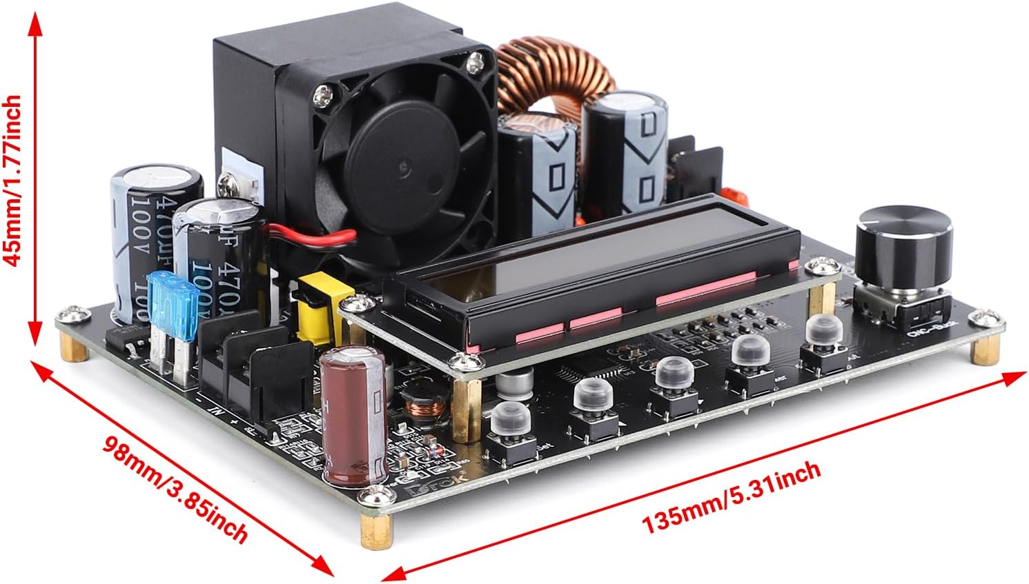
This image illustrates the physical dimensions of the buck converter module, indicating its length, width, and height for proper installation planning.
Setup
Proper setup is crucial for safe and effective operation. Ensure all connections are secure before applying power.
- Power Off: Ensure all power sources are disconnected before making any wiring connections.
- Input Wiring: Connect your DC input power source (10V-100V) to the "IN+" and "IN-" terminals on the module. Ensure correct polarity: "IN+" for positive, "IN-" for negative. The module features reverse connection protection, but correct wiring is always recommended.
- Output Wiring: Connect your load to the "OUT+" and "OUT-" terminals. Ensure correct polarity: "OUT+" for positive, "OUT-" for negative.
- Grounding: The module typically shares a common negative ground between input and output. Verify this for your specific application to avoid ground loops or unexpected behavior.
- Mounting: Secure the module in a well-ventilated area, away from conductive materials. Consider using a non-conductive enclosure if operating in an environment where accidental contact is possible.
- Initial Power On: After all connections are verified, apply power to the input. The LCD display should illuminate, showing current voltage and current readings.
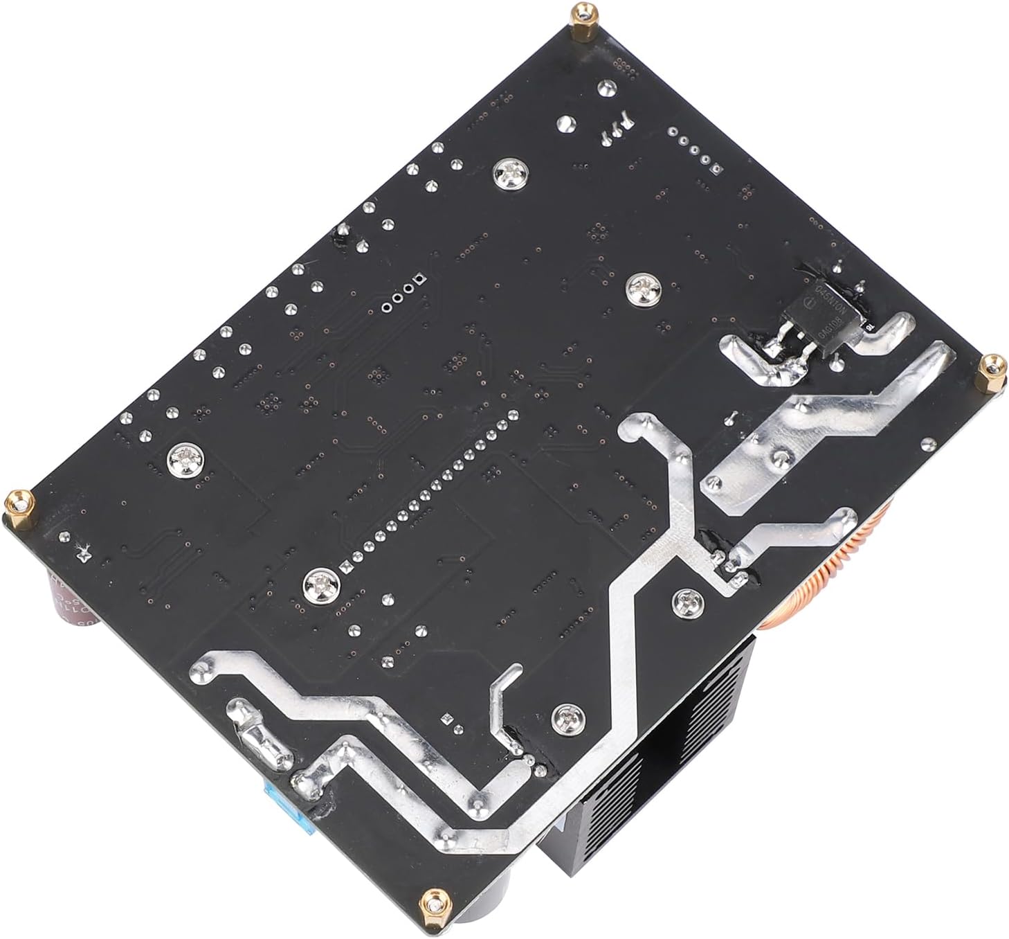
This image provides a view of the circuit board's underside, which can be helpful for understanding mounting points and general layout.
Operating Instructions
The DROK DC Buck Converter CNC is controlled via its LCD display, silicone buttons, and rotary encoder.
Setting Output Voltage and Current
- Accessing Settings: Press the "SET" button to enter the parameter setting mode. The display will show the currently adjustable parameter (e.g., output voltage).
- Navigating Parameters: Use the "SET" button to cycle through different parameters: output voltage, output current limit, and potentially other settings depending on the firmware version.
- Adjusting Values: While a parameter is selected, turn the "Rotary Encoder" (knob) clockwise to increase the value and counter-clockwise to decrease it. Short press the rotary encoder to switch between coarse and fine adjustment modes.
- Confirming Settings: Once the desired value is set, press the "OK" button (or the "SET" button again, depending on the model) to confirm and save the setting.
- Output Control: Use the "ON/OFF" button to enable or disable the output. When disabled, the module may still show input voltage but will not supply power to the output terminals.
Understanding the LCD Display
The LCD provides real-time feedback on the module's status:
- Output Voltage (V): Displays the current voltage being supplied to the load.
- Output Current (A): Shows the current being drawn by the load.
- Output Power (W): Indicates the total power being delivered.
- Input Voltage (IN V): Displays the voltage of the input power source.
- Protection Indicators: May display indicators for active protections (e.g., OVP, OCP) if triggered.
The module can be programmed to output a predetermined voltage upon power-up or only when the output button is pressed. Refer to the specific on-screen menu options for configuring this behavior.
Maintenance
Regular maintenance ensures the longevity and reliable performance of your buck converter.
- Keep Clean: Periodically clean the module, especially the fan and heatsink, to prevent dust buildup which can hinder cooling. Use a soft, dry brush or compressed air. Ensure power is disconnected before cleaning.
- Check Connections: Regularly inspect all input and output wiring connections to ensure they are tight and free from corrosion. Loose connections can lead to arcing, overheating, or unstable operation.
- Monitor Fan Operation: Ensure the cooling fan operates correctly when the output current exceeds 1.5A. A non-functional fan can lead to overheating and module damage.
- Environmental Conditions: Operate the module within its specified temperature and humidity ranges. Avoid exposure to moisture, extreme temperatures, or corrosive environments.
- Fuse Inspection: If the module fails to power on or provide output, check the 15A automotive fuse. Replace it with a fuse of the same rating if blown.
Troubleshooting
This section addresses common issues you might encounter with your DROK DC Buck Converter CNC.
| Problem | Possible Cause & Solution |
|---|---|
| No Power/Display Off |
|
| No Output Voltage |
|
| Output Voltage/Current Unstable |
|
| Fan Not Running |
|
| Incorrect Readings on LCD |
|
Warranty and Support
DROK provides a one-year service period for products purchased. If you encounter any quality issues with your DROK DC Buck Converter CNC within this period, you are eligible for a brand new replacement.
For technical assistance, troubleshooting beyond this manual, or warranty claims, please contact DROK customer support through the retailer where the product was purchased or visit the official DROK website for contact information.
When contacting support, please have your product model number (DROK-TRANSFORMER) and purchase details readily available.


