
1. Introduction
This manual provides essential information for the safe and efficient operation of your PowMr 4200W Hybrid Solar Inverter. This all-in-one unit combines the functions of an inverter, solar charger, and battery charger to provide uninterruptible power support for various applications, including home, RV, and off-grid systems. It features a pure sine wave output of 220V/230VAC from a 24VDC input and includes a built-in 120A MPPT charge controller. Please read this manual thoroughly before installation and use.

Image 1.1: PowMr 4.2KW Hybrid Solar Inverter highlighting key specifications such as 4.2KW AC output, 120A max AC charging current, 500Vdc max PV array open circuit voltage, 150V starting voltage, and 35W no-load power consumption.
2. Safety Information
Always observe the following safety precautions to reduce the risk of electric shock, fire, or injury:
- Qualified Personnel: Installation and maintenance must be performed by qualified personnel familiar with electrical systems and safety standards.
- Ventilation: Ensure adequate ventilation around the inverter to prevent overheating. Do not block ventilation openings.
- Environment: Install the inverter in a dry, cool, and dust-free environment. Avoid direct sunlight, moisture, and corrosive substances.
- Battery Safety: Batteries can produce explosive gases. Ensure proper ventilation when working with batteries. Wear eye protection.
- Grounding: The inverter must be properly grounded to prevent electric shock.
- Disconnect Power: Before performing any maintenance or wiring, disconnect all power sources (AC input, solar input, and battery).
- Overload Protection: Do not overload the inverter beyond its rated capacity.
- Emergency Shutdown: Familiarize yourself with the emergency shutdown procedures.
3. Product Overview
3.1 Key Features
- 4200W Pure Sine Wave Inverter with 120A Built-in MPPT Charge Controller.
- Dual AC Output: Main output up to 4200W, second output 840W~2940W.
- Compatible with 24V Lead-Acid (Seal, AGM, Gel, Flooded) and Lithium batteries.
- Supports charging from Solar, Utility, or Generator power.
- Comprehensive protection: Overload, Over temperature, Short circuit, Over current, Over voltage, Under voltage, Backfill, Over charge.
- RGB Light Indicator for different working modes (Stationary, PV, Battery, Utility).
- One-Click Restore Default Settings function.
- Built-in Anti-dust Kit for enhanced reliability.
3.2 Components and Indicators

Image 3.1: Front and bottom view of the inverter with labeled components. Key components include (1) LCD display, (2) Status indicator, (3) Charging indicator, (4) Fault indicator, (5) Touch Function buttons, (6) Power ON/OFF switch, (7) AC input, (8) Main output, (9) Second output, (10) PV 1 and PV 2 input, (11) RS232/WIFI/Remote LCD Communication Port, (12) Battery input, and (13) Anti-dust cover.
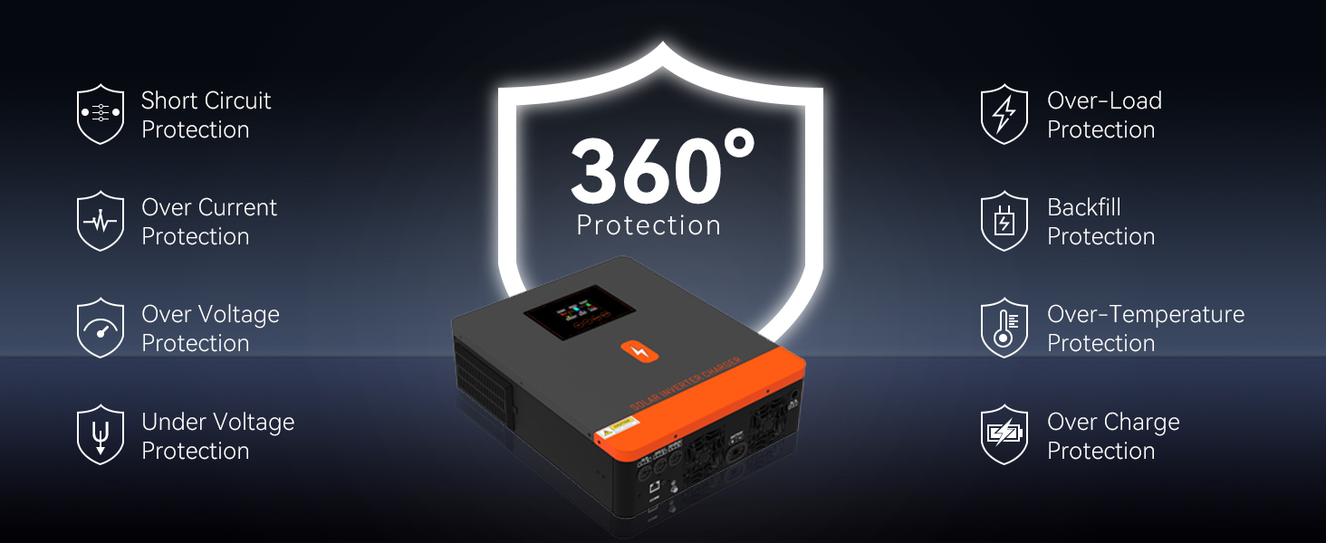
Image 3.2: The inverter offers comprehensive protection including Short Circuit, Over Current, Over Voltage, Under Voltage, Overload, Backfill, Over-Temperature, and Over Charge protection.
4. Setup and Installation
4.1 Mounting the Inverter
Mount the inverter vertically on a wall in a well-ventilated area. Ensure sufficient clearance around the unit for proper airflow and heat dissipation. Avoid mounting near flammable materials or in direct sunlight.
4.2 Wiring Connections
Follow the wiring diagram carefully. All connections must be secure and properly insulated. Use appropriate wire gauges for all connections as specified in the technical specifications.

Image 4.1: Detailed wiring diagram showing connections for AC input (from generator or main power), solar panels (PV input), battery input, and AC output to household appliances. Recommended AC wire is 12AWG with a 32A breaker. Max PV array power is 6200W, with a voltage range of 60-450Vdc. Rated battery input is 24V.
4.3 Battery Compatibility
The inverter is compatible with various 24V battery types. Ensure the correct battery type is selected in the inverter settings for optimal charging and discharge performance.

Image 4.2: The inverter supports multiple battery types including AGM, GEL, FLD (Flooded), LI (Lithium), SLD (Sealed Lead Acid), and USER-defined settings. For lithium batteries, ensure the battery type is set to 'LIb' and it will activate by solar energy after 3 seconds.
5. Operating Instructions
5.1 Powering On/Off
To power on, ensure all connections are secure, then press the Power ON/OFF switch. The LCD display will illuminate, and the inverter will begin its startup sequence. To power off, press the Power ON/OFF switch again.
5.2 LCD Display and Settings
The LCD display provides real-time operational data and allows configuration of various settings. Use the touch function buttons to navigate menus and adjust parameters. Refer to the detailed settings section in the full manual for specific parameter adjustments.
5.3 Working Mode Indicators (RGB Light)
The PowMr logo on the inverter changes color to indicate its current working mode:
- White Light: Stationary Mode
- Purple Light: PV Mode (Solar power is active)
- Red Light: Battery Mode (Operating from battery power)
- Blue Light: Utility Mode (Operating from grid/generator power)

Image 5.1: Visual representation of the RGB light patterns indicating Stationary (white), PV (purple), Utility (blue), and Battery (red) working modes.
5.4 Charger Source Priority and Output Source Priority
The inverter allows configuration of charger source priority and output source priority to optimize energy usage based on available sources (solar, utility, battery).

Image 5.2: This diagram illustrates the four configurable charger source priorities (Utility/AC Power first, Solar power first, Solar+Utility at same time, ONLY Solar) and three output source priorities (Utility Source first, Solar power first, Solar+Battery at same time).
5.5 Remote Monitoring and Control
The inverter supports remote monitoring and control via the "SMARTESS" app. A Wi-Fi module and GPRS data module are required and must be purchased separately.

Image 5.3: The inverter can be monitored and controlled remotely using the SMARTESS app, available on the App Store and Google Play. An optional Wi-Fi module (Q2721100111238) and GPRS data are required for this functionality.
6. Maintenance
Regular maintenance ensures the longevity and optimal performance of your inverter:
- Dust Removal: The built-in anti-dust kit helps protect internal components. Periodically inspect and clean the exterior of the inverter to prevent dust accumulation, especially around ventilation areas.
- Ventilation: Ensure cooling fans are free from obstructions and operating correctly. The efficient cooling system helps dissipate heat and extends inverter life.
- Connection Checks: Regularly inspect all electrical connections for tightness and signs of corrosion. Loose connections can lead to overheating and poor performance.
- Battery Inspection: Check battery terminals for corrosion and ensure they are clean and tight. Monitor battery voltage and health as per battery manufacturer guidelines.
- Environmental Conditions: Verify that the installation environment remains within the recommended temperature and humidity ranges.
7. Troubleshooting
If you encounter issues with your inverter, refer to the following common troubleshooting steps:
- No Power Output: Check AC input, solar input, and battery connections. Ensure the inverter is powered on and not in a fault state (check fault indicator). Verify battery voltage is within operating range.
- Overload Warning: Reduce the connected load. The inverter will automatically restart once the overload is removed.
- Over Temperature Warning: Ensure adequate ventilation. Clean any dust from the cooling fins and ensure fans are operational. Allow the unit to cool down.
- Charging Issues: Verify solar panel connections and voltage. Check AC input if charging from utility/generator. Ensure battery type settings are correct.
- Display Not Working: If the display is blank but the unit is operational, check for loose ribbon cables (if applicable and safe to inspect by qualified personnel).
- Incorrect Settings: Use the one-click restore default settings function if you suspect incorrect configuration.
For persistent issues or complex problems, contact PowMr customer support for assistance.
8. Specifications
| Feature | Specification |
|---|---|
| Model Name | POW-HVM4.2M |
| Item Model Number | POW-HVM4.2M-24V-N |
| Wattage | 4200 watts |
| Input Voltage | 24VDC |
| Output Voltage | 220V/230VAC |
| Max. PV Array Power | 6500W |
| Max. PV Input VOC | 500V DC |
| PV Array MPPT Voltage Range | 60-450VDC |
| Max Charging Current (AC + Solar) | 120A |
| Max AC Input Current | 100A |
| Product Dimensions | 17.4 x 14 x 4.5 inches |
| Item Weight | 17.64 pounds |
| Recommended Uses | Home, Office, Vehicle |
| Power Source | Solar and Battery Powered |
9. Warranty and Support
For warranty information and technical support, please refer to the official PowMr website or contact your authorized dealer. Keep your purchase receipt as proof of purchase for any warranty claims. Ensure you have the model number (POW-HVM4.2M-24V-N) and serial number ready when contacting support.
Online resources and FAQs may also be available on the PowMr brand store: PowMr Store on Amazon.