1. Introduction
This manual provides essential instructions for the installation, operation, and maintenance of your MokerLink 24-Port 2.5G Ethernet Switch. This unmanaged switch is designed to enhance network performance with its high-speed 2.5 Gigabit Ethernet ports and 10 Gigabit SFP+ uplinks, suitable for various environments including home offices and small businesses.
Please read this manual thoroughly before using the device to ensure proper setup and functionality.

Image 1.1: Front view of the MokerLink 24-Port 2.5G Ethernet Switch.
2. Product Overview and Key Features
The MokerLink 24-Port 2.5G Ethernet Switch is engineered for high-performance networking, offering a robust solution for expanding your network capacity.
Key Features:
- 24 x 2.5 Gigabit Ethernet Ports: Compliant with IEEE802.3bz (2.5G) standard, supporting 10/100/1000Mbps and 2.5G adaptive speeds.
- 2 x 10 Gigabit SFP+ Ports: Compatible with 1G/2.5G/10G SFP modules (modules not included), providing high-speed uplinks.
- Unmanaged Plug and Play: Requires no configuration, simplifying installation.
- Fanless Design: Ensures silent operation and reduces energy consumption.
- Durable Metal Casing: Provides robust protection and efficient heat dissipation.
- Rackmount Design: Suitable for desktop or 19-inch rack installation.
- LED Indicators: Clear status lights for power, port link, and activity.

Image 2.1: Overview of the switch's high-density 2.5G ports and 10G SFP+ uplinks.
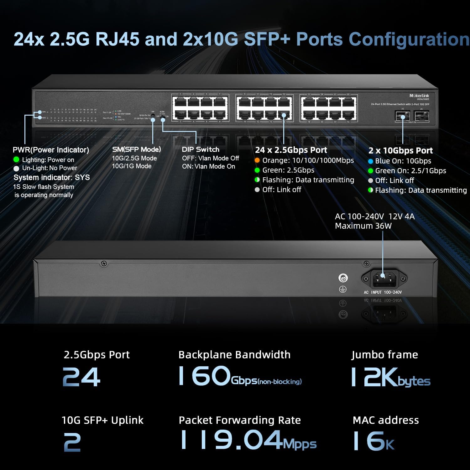
Image 2.2: Detailed port configuration, LED indicators, and power input on the switch.
3. Setup
Follow these steps for initial setup of your MokerLink Ethernet Switch.
3.1 Package Contents
- MokerLink 24-Port 2.5G Ethernet Switch
- Power Cord
- Rackmount Kit (if included with your model)
3.2 Connecting the Switch
- Power Connection: Connect the provided power cord to the AC input on the rear panel of the switch and then to a standard AC power outlet (100-240V AC, 50/60Hz). The Power LED on the front panel should illuminate.
- Ethernet Device Connection: Connect your network devices (e.g., computers, NAS, WiFi 6 APs, servers) to the 2.5G Ethernet ports (ports 1-24) using Cat5e, Cat6, or Cat6a Ethernet cables. The switch supports auto MDI/MDIX and auto-negotiation for speed.
- Uplink Connection (Optional): For high-speed network backbone connections, insert compatible 1G/2.5G/10G SFP+ modules into the SFP+ ports (ports 25-26) and connect them to your core network devices using appropriate fiber optic cables.

Image 3.1: Ethernet cables connected to the 2.5G ports and SFP+ modules in the uplink ports.
3.3 Rack Mounting (Optional)
The switch can be installed in a standard 19-inch equipment rack. Attach the included rackmount brackets to the sides of the switch using the provided screws, then secure the switch into the rack.

Image 3.2: Example of MokerLink switches installed in a 19-inch rack.
4. Operating the Switch
The MokerLink 24-Port 2.5G Ethernet Switch is an unmanaged device, meaning it operates without requiring complex configuration. Once connected, it functions automatically.
4.1 LED Indicators
The front panel LEDs provide visual status of the switch's operation:
- PWR (Power Indicator):
- Lighting On: Power is supplied.
- Un-Light: No power.
- SYS (System Indicator):
- Slow Flash: System is operating normally.
- 2.5G Ethernet Ports (1-24) Link/Activity LEDs:
- Orange: 10/100/1000Mbps link.
- Green: 2.5Gbps link.
- Off: No link.
- Flashing: Data transmitting/receiving.
- 10G SFP+ Ports (25-26) Link/Activity LEDs:
- Blue On: 10Gbps link.
- Green On: 2.5Gbps link.
- Off: No link.
- Flashing: Data transmitting/receiving.
4.2 VLAN Mode (DIP Switch)
This switch features a DIP switch for enabling or disabling VLAN mode. When VLAN mode is enabled (ON), ports 1-22 are isolated from each other but can communicate with the uplink ports (25-26). This feature can enhance network security and performance by segmenting traffic.
- DIP Switch OFF: VLAN Mode is disabled. All ports can communicate freely.
- DIP Switch ON: VLAN Mode is enabled. Ports 1-22 are isolated from each other but can communicate with uplink ports 25-26.

Image 4.1: Illustration of port-based VLAN operation, isolating ports 1-22 while allowing communication with uplinks.
5. Maintenance
To ensure the longevity and optimal performance of your MokerLink switch, consider the following maintenance guidelines:
- Environmental Conditions: Operate the switch within its specified temperature and humidity ranges. Avoid placing it in direct sunlight, near heat sources, or in areas with excessive dust or moisture.
- Cleaning: Periodically clean the exterior of the switch with a soft, dry cloth. Do not use liquid or aerosol cleaners. Ensure ventilation openings are clear of obstructions.
- Fanless Design: The fanless design eliminates the need for internal fan cleaning and reduces noise, contributing to stable and quiet operation.
- Cable Management: Ensure all connected cables are neatly organized and not under strain to prevent accidental disconnections or damage.

Image 5.1: Illustration of the fanless design and heat dissipation.
6. Troubleshooting
If you encounter issues with your MokerLink switch, refer to the following common troubleshooting steps:
- No Power:
- Ensure the power cord is securely connected to both the switch and a working power outlet.
- Verify the power outlet is functional by plugging in another device.
- No Link Light on a Port:
- Check if the Ethernet cable is securely connected at both ends (switch and device).
- Try a different Ethernet cable to rule out cable failure.
- Ensure the connected device is powered on and its network adapter is functioning correctly.
- Verify the SFP/SFP+ module is correctly inserted and compatible if using fiber ports.
- Slow Network Speed:
- Confirm that your connected devices and cables support 2.5G or 10G speeds. Using older Cat5 cables may limit performance.
- Check the port LED color to confirm the negotiated speed (Green for 2.5G, Orange for 1G/100M/10M on Ethernet ports; Blue for 10G, Green for 2.5G on SFP+ ports).
- Ensure there are no excessive network loops or broadcast storms on your network.
- Intermittent Connectivity:
- Inspect cables for damage.
- Ensure the switch is placed in a well-ventilated area to prevent overheating.
- Temporarily disable VLAN mode via the DIP switch to see if it resolves the issue.
7. Specifications
| Feature | Specification |
|---|---|
| Model Number | 24*2.5G |
| Brand | MokerLink |
| Number of Ports | 24 x 2.5G Base-T, 2 x 10G SFP+ |
| Data Transfer Rate | 160 Gbps (Backplane Bandwidth) |
| Packet Forwarding Rate | 119.04 Mpps |
| MAC Address Table Size | 16K |
| Interface Type | RJ45, SFP+ |
| Power Input | AC 100-240V, 12V 4A (Maximum 36W) |
| Case Material | Metal |
| Color | Black |
| Item Weight | 6.89 pounds |
| Package Dimensions | 20 x 11.5 x 3.5 inches |
| Upper Temperature Rating | 50 Degrees Celsius |
| Included Components | 2.5Gigabit Switch |
8. Warranty and Support
For warranty information and technical support, please refer to the official MokerLink website or contact your vendor. Keep your purchase receipt for warranty claims.
You can visit the MokerLink Store for additional product information and support resources: MokerLink Store