1. Introduction
This manual provides detailed instructions for the installation, operation, and maintenance of your SODOLA 16-Port Gigabit PoE+ Unmanaged Network Switch. This device is designed to provide reliable network connectivity and Power over Ethernet (PoE) capabilities for various network devices. Please read this manual thoroughly before using the product to ensure proper setup and functionality.
2. Product Overview
2.1 Key Features
- 18-Port Gigabit Ethernet: Features 16 Gigabit PoE ports and 2 Gigabit uplink ports. Each port supports 10/100/1000M self-adaptive, automatic negotiation in duplex mode, and Auto MDI/MDIX.
- 400W Power Budget: Supports IEEE 802.3af/at standard with an output power of 15.4W/30W per port, and a total power supply of up to 400W. This allows multiple ports to operate at full power under the AT (30W) standard.
- VLAN Mode: Provides fixed VLAN for port isolation, preventing communication between PoE ports while allowing communication with uplink ports to reduce network congestion.
- Plug and Play: Automatic device detection requires no configuration; simply connect the power cord and network cables.
- Universal Compatibility: Supports both PoE devices (e.g., IP cameras, EAPs, access points, IP phones) and Non-PoE devices (data transmission only).
- Durable Design: Features a metal casing, silent fanless operation, wide operating temperature range (-10°C to 50°C), and 1U rackmount capability.
- High Performance: Offers 36Gbps backplane bandwidth and 10KB Jumbo Frame support.
2.2 Package Contents
- SODOLA 16-Port Gigabit PoE+ Unmanaged Network Switch
- Power Cord
- User Manual (this document)

Figure 1: Front view of the SODOLA 16-Port Gigabit PoE+ Unmanaged Network Switch.

Figure 2: Overview of the switch highlighting 16 Gigabit PoE ports, 2 Gigabit uplink ports, 400W total PoE budget, 36Gbps backplane bandwidth, and 10KB Jumbo Frame support.
3. Setup
The SODOLA 16-Port Gigabit PoE+ Unmanaged Network Switch is designed for simple plug-and-play installation. Follow these steps to set up your device:
- Connect to Power: Connect the provided power cord to the switch's power input and then to a standard AC power outlet. Ensure the power indicator light on the switch illuminates.
- Connect Uplink Ports: Connect your router or main network device to one of the two Gigabit uplink ports (labeled G1/G2) on the switch using a standard Ethernet cable. These ports are designed for high-speed connection to your core network.
- Connect PoE Devices: Connect your PoE-compatible devices (e.g., IP cameras, wireless access points, IP phones) to any of the 16 PoE ports (labeled 1-16) using standard Ethernet cables. The switch will automatically detect and provide power to these devices if they are IEEE 802.3af/at compliant.
- Connect Non-PoE Devices (Optional): If you have non-PoE devices (e.g., computers, printers, NVRs) that require network connectivity but not power from the switch, you can connect them to any of the 16 PoE ports. Note that these devices will only receive data and will require their own power supply. Alternatively, an active PoE splitter can be used for non-PoE devices to receive power from the switch.
- Verify Connections: Check the LED indicators on the front panel for each connected port. A solid green or amber light typically indicates a successful link and activity.

Figure 3: Diagram illustrating the simple three-step plug-and-play setup process: Connect to Power, Connect Devices (IP Phone, IP Camera, Wireless AP, Router), and Enjoy.
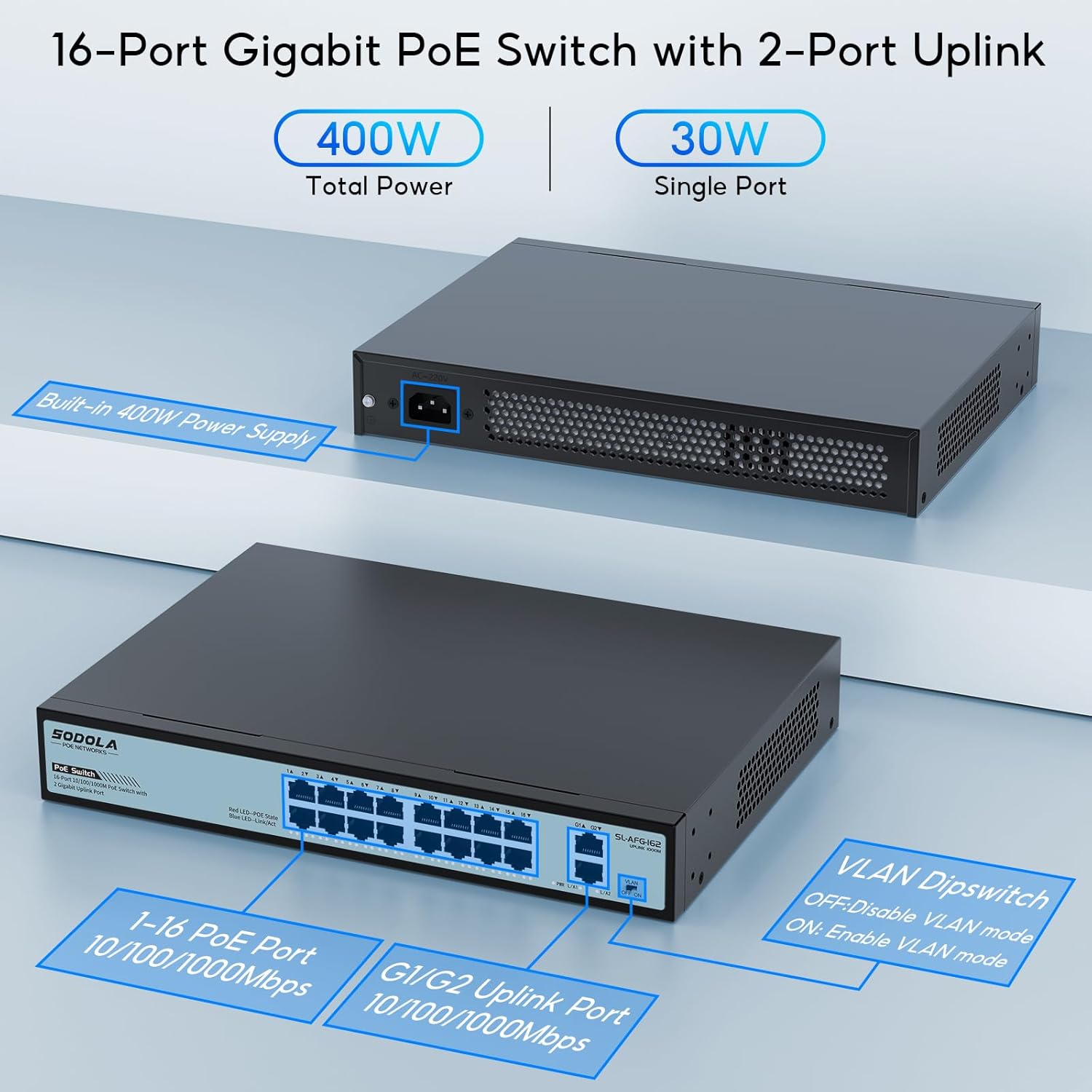
Figure 4: Detailed view of the switch ports, including 1-16 PoE ports and G1/G2 uplink ports, along with the VLAN dipswitch.
4. Operating Instructions
4.1 Basic Operation
Once the switch is powered on and devices are connected, it operates automatically. As an unmanaged switch, it requires no software configuration for basic network functionality. Data traffic will flow between connected devices and to the uplink ports.
4.2 Power over Ethernet (PoE)
The switch automatically detects and supplies power to IEEE 802.3af/at compliant PoE devices connected to ports 1-16. The total power budget is 400W, ensuring sufficient power for multiple devices. If a connected device is not PoE-compatible, the switch will only transmit data.
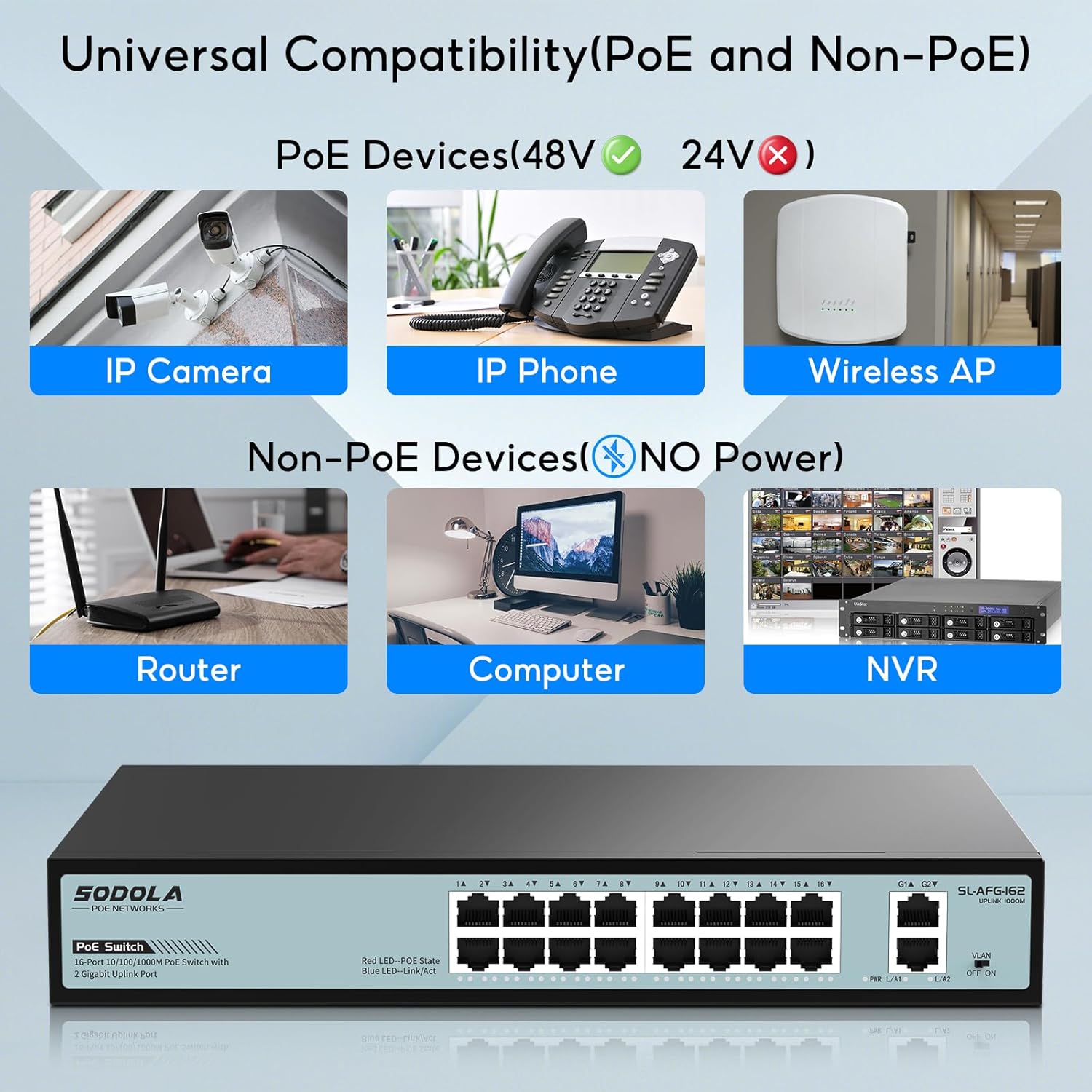
Figure 5: Illustration of the switch's compatibility with various PoE devices (IP Camera, IP Phone, Wireless AP) and Non-PoE devices (Router, Computer, NVR).
5. VLAN Mode
The SODOLA switch includes a VLAN (Virtual Local Area Network) dipswitch for port isolation. This feature enhances network security and reduces network congestion by segmenting traffic.
5.1 Enabling/Disabling VLAN Mode
Locate the VLAN dipswitch on the front panel of the switch. It typically has two positions: OFF and ON.
- OFF (Default - Switch Mode): In this mode, the switch operates as a general network switch. All ports can communicate with each other, and all ports support Gigabit auto-negotiation. This is suitable for most standard network setups.
- ON (VLAN Mode): When set to ON, fixed VLANs are enabled. In this mode, the 16 PoE ports (ports 1-16) are isolated from each other. They cannot communicate directly with each other but can communicate with the uplink ports (G1/G2). This is particularly useful for security applications, such as IP camera networks, where you want to prevent devices on different PoE ports from interacting directly, thereby reducing potential network congestion and enhancing security.
Caution: Changing the VLAN mode will affect network communication between devices connected to the PoE ports. Ensure this mode is appropriate for your network configuration before enabling it.

Figure 6: Illustration of the VLAN dipswitch and the operational differences between Switch Mode (VLAN OFF) and VLAN Mode (VLAN ON).
6. Maintenance
To ensure optimal performance and longevity of your SODOLA switch, follow these maintenance guidelines:
- Cleaning: Periodically clean the exterior of the switch with a soft, dry cloth. Do not use liquid or aerosol cleaners.
- Ventilation: Ensure the switch is placed in a well-ventilated area. Do not block the ventilation openings on the sides of the device. The fanless design relies on natural convection for cooling.
- Environment: Operate the switch within its specified temperature and humidity ranges. Avoid exposing it to extreme temperatures, direct sunlight, or high moisture.
- Cable Management: Keep network cables organized and free from kinks or excessive bends to prevent signal degradation.

Figure 7: The fanless design of the switch ensures silent operation and efficient heat dissipation through ventilation.
7. Troubleshooting
If you encounter issues with your SODOLA switch, refer to the following troubleshooting tips:
- No Power: Ensure the power cord is securely connected to both the switch and the power outlet. Verify the power outlet is functional. Check the power indicator LED on the switch.
- No Link/Activity: Check if the Ethernet cables are securely connected to both the switch port and the connected device. Ensure the connected device is powered on and functioning correctly. Try a different Ethernet cable or port.
- PoE Device Not Receiving Power: Verify that the connected device is IEEE 802.3af/at compliant. Check the PoE status LED for the specific port. Ensure the total power consumption of all connected PoE devices does not exceed the 400W power budget.
- Network Congestion/Slow Speed: If VLAN mode is OFF, consider enabling it to isolate traffic between PoE ports, especially in networks with many devices or high traffic. Ensure all cables are Gigabit-rated for optimal performance.
- Intermittent Connectivity: Check for loose cable connections. Ensure the switch is not overheating (though designed for wide operating temperatures, extreme conditions can affect performance).
If problems persist after attempting these steps, please contact SODOLA customer support for further assistance.
8. Specifications
| Feature | Specification |
|---|---|
| Brand | Sodola |
| Model Number | 16xPoE+2GE |
| Number of Ports | 18 (16 PoE, 2 Uplink) |
| Data Transfer Rate | 1000 Megabits Per Second (Gigabit) |
| PoE Standard | IEEE 802.3af/at |
| Total PoE Power Budget | 400W |
| Interface Type | PoE |
| Case Material | Metal |
| Product Dimensions | 11.81 x 8.27 x 1.81 inches |
| Item Weight | 5.92 pounds |
| Rackmount | 1U Rackmount |
| Compatible Devices | Desktop, Laptop, Router, Printer, IP Camera, Access Point |
9. Safety Information
- Do not open the device casing. There are no user-serviceable parts inside.
- Keep the device away from water, fire, high humidity, or hot environments.
- Ensure the power supply voltage matches the requirements specified on the device label.
- Use only the power adapter provided with the device.
- Avoid placing heavy objects on the switch.
- Disconnect the power cable before cleaning or if the device will not be used for an extended period.
10. Warranty and Support
SODOLA products are designed for reliability and performance. This product comes with a standard manufacturer's warranty. For specific warranty terms and conditions, please refer to the documentation included with your purchase or visit the official SODOLA website.
For technical support, troubleshooting assistance, or any product-related inquiries, please contact SODOLA customer service through their official channels. Information regarding extended protection plans may also be available from your retailer.


