
1. Introduction
This manual provides essential information for the safe and effective installation, operation, and maintenance of your DeWin GYHC series modular AC contactor. Please read this manual thoroughly before installation and retain it for future reference. This contactor is designed for various applications including remote control, lighting, heating, ventilation, rolling shutters, public hot water systems, mechanical ventilation systems, and low-inductance micro-inductance load environments.
2. Safety Information
WARNING: Electrical shock hazard. Installation and maintenance should only be performed by qualified personnel.
- Always disconnect power before installing, wiring, or servicing the contactor.
- Ensure all wiring complies with local and national electrical codes.
- Verify that the supply voltage and current ratings match the contactor's specifications.
- Do not operate the contactor if it is damaged or appears to be malfunctioning.
- Wear appropriate personal protective equipment (PPE) when working with electrical systems.
3. Product Overview
The DeWin GYHC-63 modular AC contactor is a compact device designed for reliable switching of electrical loads. It features a robust construction suitable for DIN rail mounting.

Figure 3.1: Front view of the DeWin GYHC-63 AC Contactor, showing terminals and model information.
3.1. Component Identification

Figure 3.2: Detailed view of the contactor highlighting key components such as terminals, wiring diagram, parameters, and the instruction window.
- Terminals (1, 3, 5, 7, A1, A2, 2, 4, 6, 8): Connection points for control and load circuits.
- Wiring Diagram: Printed on the unit for quick reference.
- Parameter Information: Displays key electrical ratings.
- Instruction Window: Indicates the contactor's current state (e.g., ON/OFF).
- DIN Rail Clip: Located on the side for secure mounting on a 35mm DIN rail.
4. Specifications
The following table details the technical specifications for the DeWin GYHC-63 AC Contactor (63A variant):

Figure 4.1: Product information and dimensions of the DeWin GYHC-63 AC Contactor.
| Feature | Specification |
|---|---|
| Model Type | 4P 63A 4NO-AC230V |
| Control Voltage | AC 230V |
| Rated Voltage | AC 400V |
| AC-7a Rated Current | 63A |
| AC-7b Rated Current | 20A |
| Contact Configuration | 4NO (4 Normally Open contacts) |
| Electric Shock Resistance | 2 times |
| Frequency | 50Hz |
| Electrical Life | 100,000 times |
| Maximum Switching Operations per Day | 100 times |
| Insulation Voltage | 500V AC |
| Pollution Degree | 2 |
| Rated Impulse Withstand Voltage | 4kV |
| Protection Class (Contactor Body) | IP20 |
| Protection Class (Installed in Distribution Box) | IP40 |
| Working Temperature | -5℃ to +60℃ |
| Storage Temperature | -40℃ to +70℃ |
| Humidity and Heat Resistance | Level 2 (55℃, 95% relative humidity) |
| Dimensions (approx.) | 85mm (H) x 54mm (W) x 68mm (D) |
| Weight | 230g |
5. Installation
The DeWin GYHC-63 contactor is designed for standard 35mm DIN rail mounting. Ensure power is disconnected before proceeding.
5.1. Mounting on DIN Rail
- Locate the 35mm DIN rail in your electrical distribution box.
- Align the contactor's DIN rail clip with the rail.
- Press the contactor firmly onto the rail until it clicks into place. Ensure it is securely fastened.
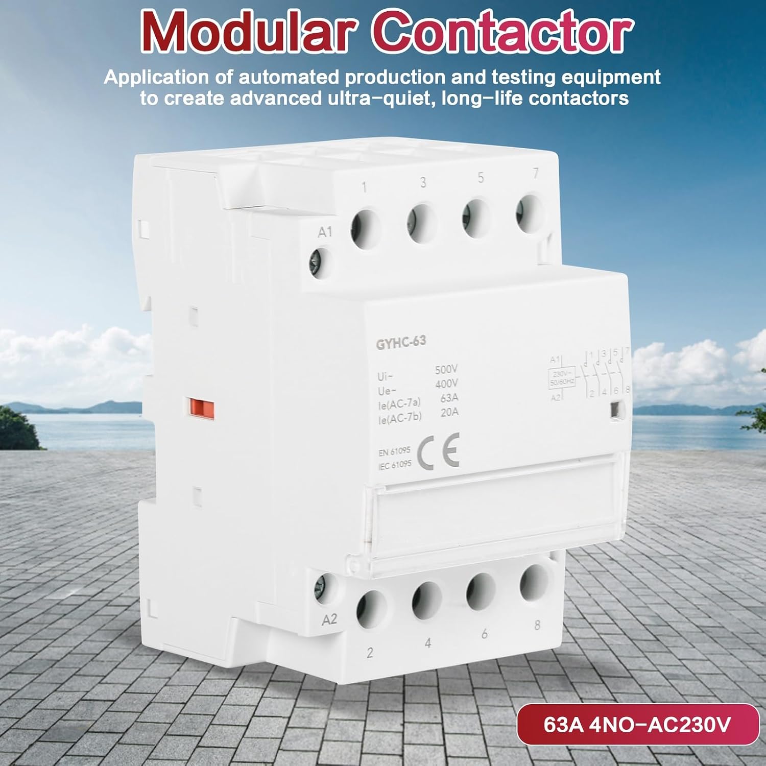
Figure 5.1: The modular contactor shown securely mounted on a standard 35mm DIN rail, demonstrating its ease of installation.
5.2. Wiring Diagram and Connections
Refer to the wiring diagram printed on the contactor and the example below for correct connections. The contactor features 4 Normally Open (4NO) contacts.

Figure 5.2: A 230V wiring example for the DeWin GYHC-63 AC Contactor, illustrating connections for neutral wire, live wire, and control devices.
- Control Circuit (Coil): Connect the AC 230V control voltage to terminals A1 and A2. When voltage is applied to A1-A2, the contactor coil energizes, closing the main contacts.
- Load Circuit (Main Contacts): Connect the live wire (L) to terminals 1, 3, 5, and 7. Connect the neutral wire (N) or load output to terminals 2, 4, 6, and 8. Ensure proper phase sequence if applicable.
- Tighten all terminal screws securely to prevent loose connections, which can cause overheating or arcing.
- After wiring, double-check all connections for correctness and security before restoring power.
6. Operating Instructions
The DeWin GYHC-63 contactor operates by receiving a control voltage at its coil terminals (A1-A2). When the control voltage (AC 230V) is applied, the electromagnetic coil energizes, causing the main contacts (1-2, 3-4, 5-6, 7-8) to close, thereby connecting the load to the power supply. When the control voltage is removed, the coil de-energizes, and the contacts open, disconnecting the load.
- The contactor is suitable for switching various resistive and slightly inductive loads.
- The instruction window on the front of the contactor provides a visual indication of its operational status (e.g., engaged or disengaged).
- Ensure the load current does not exceed the rated AC-7a (63A) or AC-7b (20A) current for the respective load types.
7. Maintenance
The DeWin GYHC-63 contactor is designed for long-term, reliable operation with minimal maintenance. However, periodic checks are recommended to ensure optimal performance and safety.
- Visual Inspection: Regularly inspect the contactor for any signs of physical damage, discoloration, or loose connections.
- Terminal Tightness: Periodically check and re-tighten terminal screws to ensure good electrical contact.
- Cleaning: Keep the contactor free from dust and debris. Use a dry, soft cloth for cleaning. Do not use solvents or abrasive cleaners.
- Operational Check: If possible and safe to do so, periodically verify the contactor's switching action and ensure the instruction window indicates the correct status.
Always disconnect power before performing any maintenance.
8. Troubleshooting
If you encounter issues with your DeWin GYHC-63 contactor, consider the following common troubleshooting steps:
- Contactor Does Not Energize:
- Check if the control voltage (AC 230V) is present at terminals A1 and A2.
- Verify that the control circuit wiring is correct and secure.
- Ensure there are no internal faults (though rare, this may require replacement).
- Contactor Energizes but Load Does Not Receive Power:
- Check the main load circuit wiring (terminals 1-2, 3-4, 5-6, 7-8).
- Ensure the load is correctly connected and not faulty.
- Verify that the main contacts are closing properly (visually inspect the instruction window).
- Overheating:
- Ensure the load current does not exceed the contactor's rated current.
- Check for loose terminal connections.
- Ensure adequate ventilation around the contactor.
If the problem persists after troubleshooting, consult a qualified electrician or contact customer support.
9. Warranty and Support
For warranty information and technical support, please refer to the product packaging or contact your point of purchase. Keep your purchase receipt as proof of purchase.