1. Introduction
This manual provides comprehensive instructions for the installation, operation, and maintenance of the POWLSOJX MPPT Solar Charge Controller 60A. This device is designed to efficiently manage power flow from solar panels to various battery types, including lead-acid and lithium batteries, across 12V, 24V, 36V, and 48V systems. It features an intuitive LCD display for real-time monitoring and dual USB ports for convenience.
Key features include:
- Versatile Operation Modes: Seven distinct modes for charging, light control, time-delay control, general control, manual control, timing control, and factory test mode.
- Intuitive LCD Display: Provides real-time information on battery and solar panel status, mode control, load output status, and various parameters for easy monitoring.
- Efficient MPPT Charging: Automatic Maximum Power Point Tracking (MPPT) ensures optimal charging efficiency and maximized power conversion from solar panels.
- Flexible Discharge Control: Multiple discharge modes to manage the discharge process based on specific needs.
- Wide Compatibility and Protection: Supports 12V, 24V, 36V, and 48V systems with protective features including low-voltage protection and recommended installation sequences.
2. Safety Information
Please read all safety instructions carefully before installation and operation. Failure to follow these instructions may result in electric shock, fire, or serious injury.
- Ensure all wiring is performed by qualified personnel.
- Always disconnect power from solar panels and batteries before installing or servicing the controller.
- Use appropriate circuit breakers and fuses for all connections to prevent overcurrent.
- Do not expose the controller to water or excessive humidity.
- Install the controller in a well-ventilated area to prevent overheating.
- Verify correct polarity for all connections (positive to positive, negative to negative). Incorrect polarity can damage the controller and connected devices.
- Keep children away from the solar power system components.
3. Product Overview and Features
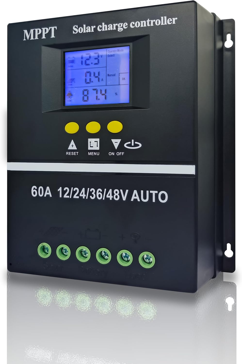
Figure 1: Front view of the POWLSOJX MPPT Solar Charge Controller 60A, showing the LCD screen, control buttons, and connection terminals.
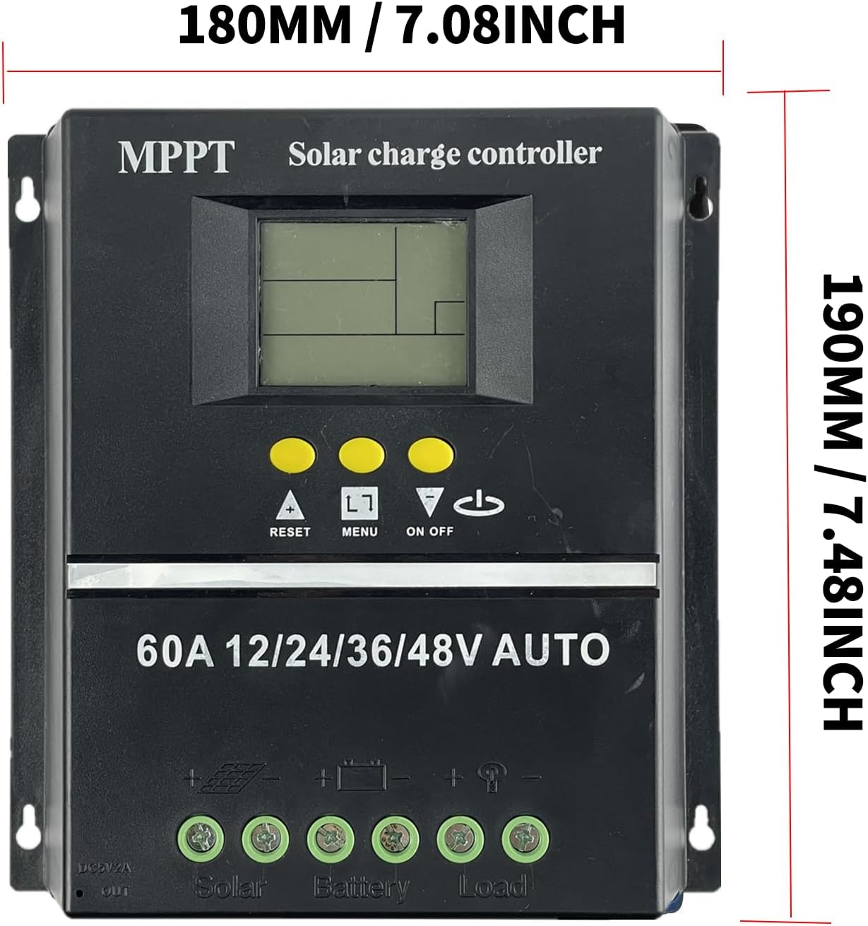
Figure 2: Dimensions of the solar charge controller, approximately 180mm (7.08 inches) wide and 190mm (7.48 inches) high.
3.1 Protection Functions
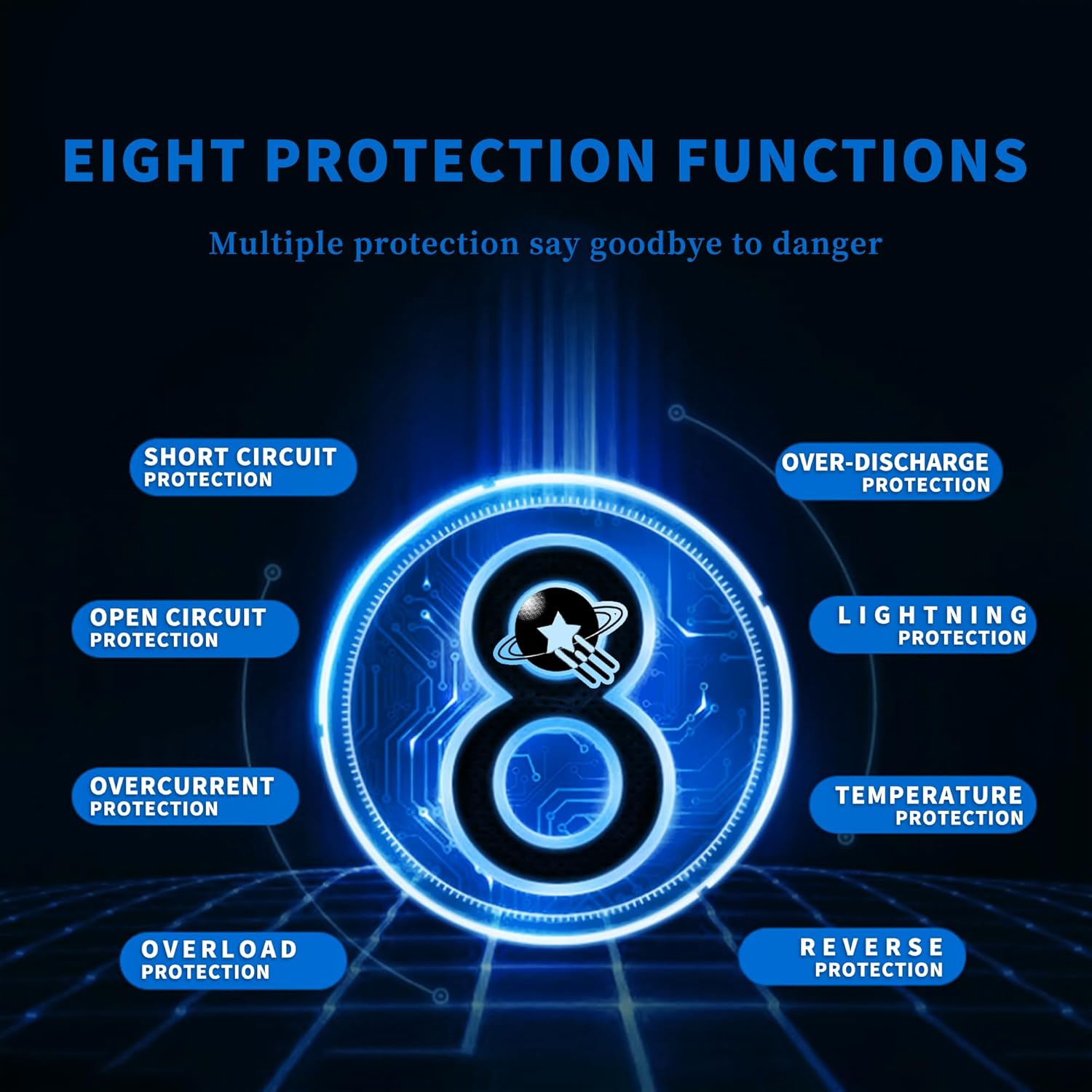
Figure 3: The controller incorporates eight essential protection functions to ensure system safety and longevity.
The controller is equipped with multiple protection mechanisms:
- Short Circuit Protection: Prevents damage from short circuits in the system.
- Open Circuit Protection: Safeguards against open circuit conditions.
- Overcurrent Protection: Protects against excessive current flow.
- Overload Protection: Prevents damage from excessive load.
- Over-Discharge Protection: Extends battery life by preventing deep discharge.
- Lightning Protection: Offers defense against lightning strikes.
- Temperature Protection: Monitors and manages internal temperature to prevent overheating.
- Reverse Protection: Protects against incorrect polarity connections.
3.2 Efficient Heat Dissipation

Figure 4: The controller features a die-cast aluminum heat sink for efficient heat dissipation.

Figure 5: Detail of the aluminum alloy heat sink, designed for effective cooling and ventilation.
The controller incorporates a die-cast aluminum heat sink, providing high heat dissipation efficiency. This design ensures stable operation and extends the lifespan of the device. Additionally, a temperature sensor (3.3ft length) is included to compensate battery charge voltages, further extending battery lifespan. This sensor should be placed near the battery.
3.3 LCD Display and Interface

Figure 6: The LCD display provides clear, real-time operational data.

Figure 7: The controller features dual USB ports and a dedicated load interface for versatile connectivity.
The large LCD display offers a simple interface for monitoring and management. It shows battery voltage, charging current, battery state of charge, and selected operating modes. The controller also includes dual USB ports for charging external devices and a dedicated load interface.
4. Specifications
| Feature | Specification |
|---|---|
| Brand | POWLSOJX |
| Model Number | 60A |
| Voltage Compatibility | 12V, 24V, 36V, 48V (Auto-sensing) |
| Display Type | LCD |
| Battery Types Supported | Lead Acid, Lithium Batteries |
| Item Weight | 1.68 pounds |
| Package Dimensions | 7.99 x 7.76 x 2.95 inches |
| Color | Black |
| UPC | 715748231288 |
4.1 System Connection Diagram and Power Ratings

Figure 8: A typical system connection diagram illustrating the integration of the solar charge controller with solar panels, battery, inverter, and loads.
| Model | SY-SLCD-60 (60A) | |||
|---|---|---|---|---|
| Battery Voltage | 12V | 24V | 36V | 48V |
| Recommended PV Input Voltage | 15V-25V | 30V-50V | 45V-75V | 60V-100V |
| Maximum PV Input Power | 720W | 1440W | 2160W | 2880W |
5. Setup and Installation
Proper installation is crucial for the safe and efficient operation of your solar charge controller. Follow these steps carefully.
5.1 Connection Order

Figure 9: Correct installation connection order for the solar charge controller.
The correct connection order is critical to prevent damage to the controller and other components.
- Connect the Battery (1): First, connect the battery to the controller. Ensure correct polarity (positive to positive, negative to negative). The controller will automatically detect the battery voltage (12V, 24V, 36V, or 48V).
- Connect the DC Load (2): Next, connect your DC loads to the controller's load terminals.
- Connect the PV Panel (3): Finally, connect the solar panels to the controller's PV input terminals.
Important Wiring Instructions:
- To correctly identify the battery voltage, ensure the battery voltage is above a minimum threshold before connecting:
- 12V battery: Voltage higher than 10V
- 24V battery: Voltage higher than 20V
- 36V battery: Voltage higher than 30V
- 48V battery: Voltage higher than 42V
- Do not charge 12V batteries with 24V/36V/48V solar panels if the voltage difference is too large, as this may damage the controller due to overheating.
- It is recommended to integrate an air switch for additional protection.

Figure 10: Wiring instructions and compatibility notes for different battery and solar panel configurations.
6. Operating Instructions
The controller offers various operating modes to suit different application needs. Use the LCD display and control buttons to navigate and select modes.
6.1 Control Buttons
- RESET: Resets the controller.
- MENU: Navigates through menu options and confirms selections.
- UP/DOWN Arrows: Adjusts parameters and scrolls through options.
- ON/OFF: Toggles load output (in manual control mode).
6.2 Operation Modes
The controller supports seven distinct working modes:
- Charging Mode: The controller focuses solely on charging the battery and does not discharge power to loads.
- Light Control Mode: When the controller detects nighttime, it will delay for ten minutes, then begin discharging to the load. When it detects daytime, it will delay for ten minutes, then stop discharging.
- Light and Time Delay Control Mode: Similar to Light Control Mode, but after detecting nighttime and the ten-minute delay, it starts discharging and counts down for a set duration. Discharge stops when the timer reaches zero. The maximum duration for this delay is 23 hours and 59 minutes.
- Universal Control Mode: Under normal operating conditions, the controller continuously discharges power to the load.
- Manual Control Mode: Discharge to the load can be manually toggled ON or OFF using the 'DOWN' button.
- Timing Control Mode: Allows for scheduled opening or closing of the discharge output at specific times.
- Test Mode: Functions similarly to Light and Time Delay Control Mode but with a reduced ten-minute time delay for testing purposes.
Low Voltage Protection Override: The controller will normally stop discharging under low voltage conditions to protect the battery. However, by touch-holding the 'DOWN' button for 5 seconds, discharge can be manually continued. Be aware that this action may damage the battery and should be used with caution.
7. Maintenance
Regular maintenance ensures optimal performance and longevity of your solar charge controller.
- Cleanliness: Keep the controller clean and free from dust and debris. Use a dry cloth for cleaning.
- Connections: Periodically check all wiring connections for tightness and corrosion. Loose connections can lead to power loss or overheating.
- Ventilation: Ensure the installation area remains well-ventilated to allow for proper heat dissipation. Do not block the heat sink fins.
- Battery Health: Monitor battery voltage and health regularly. Ensure batteries are within their recommended operating parameters.
- Environmental Check: Inspect the controller for any signs of physical damage, moisture ingress, or pest infestation.
8. Troubleshooting
This section addresses common issues you might encounter with your solar charge controller.
- Controller Not Powering On / Blinking Screen:
- Check Battery Connection: Ensure the battery is connected first and with correct polarity.
- Battery Voltage: Verify the battery voltage meets the minimum threshold for detection (e.g., >10V for 12V battery). A completely discharged battery may not be detected.
- Wiring: Double-check all wiring for loose connections or incorrect polarity.
- No Charging / Low Charging Current:
- PV Panel Connection: Ensure solar panels are connected last and with correct polarity.
- PV Voltage: Verify the solar panel input voltage is within the recommended range for your battery system (refer to Section 4.1).
- Sunlight: Ensure adequate sunlight is reaching the solar panels.
- MPPT Functionality: While this is an MPPT controller, ensure the voltage difference between PV and battery is sufficient for efficient operation.
- No Load Output:
- Load Connection: Check load wiring for correct polarity and secure connections.
- Operating Mode: Verify the controller is in an appropriate discharge mode (e.g., Universal, Light Control, Manual ON).
- Low Voltage Disconnect: The controller may have disconnected the load due to low battery voltage. Recharge the battery.
- Manual Override: If in low voltage protection, you can temporarily override by holding the 'DOWN' button for 5 seconds (use with caution).
- Overheating:
- Ventilation: Ensure the controller is installed in a well-ventilated area and the heat sink fins are not obstructed.
- Load/PV Mismatch: Ensure the connected solar panel power and load are within the controller's specifications.
9. Warranty and Support
For warranty information and technical support, please refer to the product packaging or contact POWLSOJX customer service through your point of purchase. Keep your purchase receipt as proof of purchase.


