1. Introduction
The Optex AP-360B(C) is an indoor recessed mount Passive Infrared (PIR) detector designed for discreet motion detection in various indoor environments. This device utilizes passive infrared technology to detect movement within a 360-degree area, providing reliable security monitoring. Its compact design allows for seamless integration into ceilings, making it suitable for large rooms or corner areas where traditional sensors might be conspicuous.
This manual provides essential information for the proper installation, operation, and maintenance of your AP-360B(C) detector. Please read it thoroughly before installation and retain it for future reference.
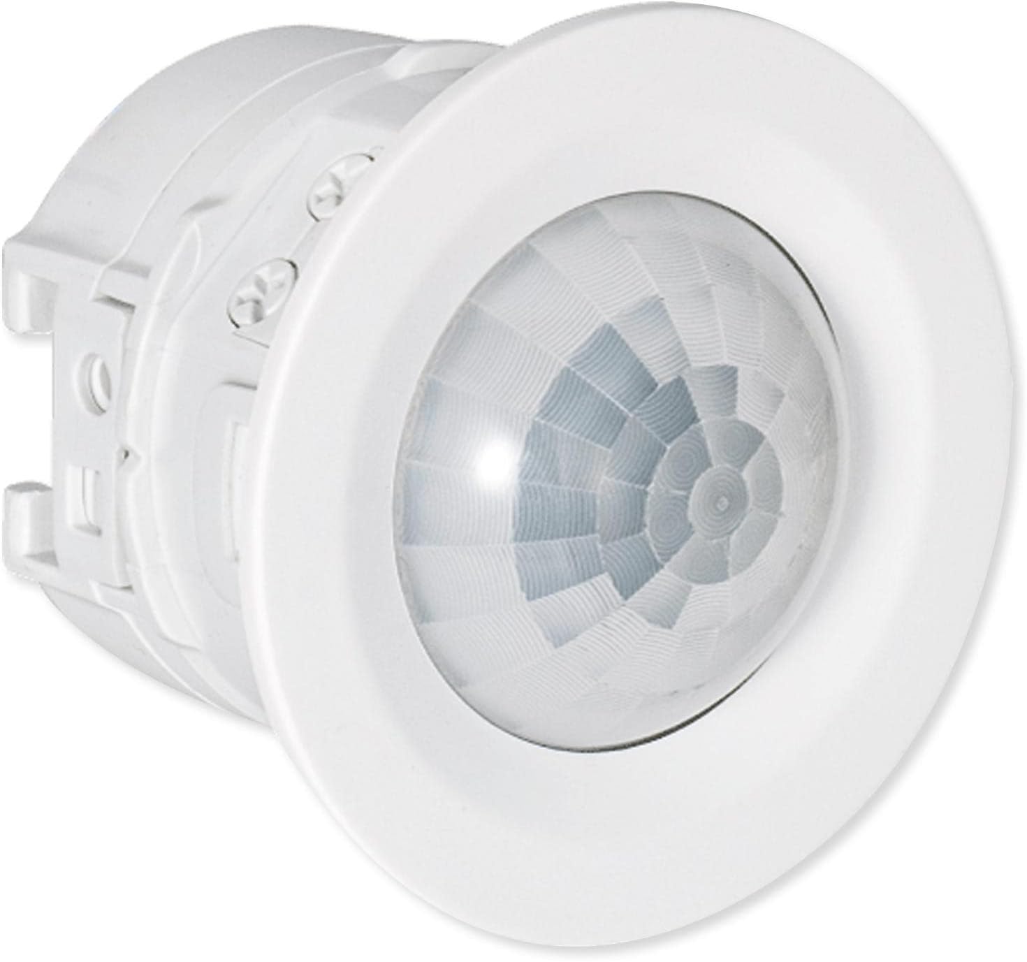
Figure 1: Front view of the Optex AP-360B(C) Indoor Recessed Mount PIR Detector. This image shows the compact, circular design of the detector, which is intended for discreet ceiling installation.
2. Product Overview
Key Features:
- 360-degree detection area, covering up to 20 feet (6 meters) at a mounting height of 14 feet 9 inches (4.5 meters).
- Compact design for discreet, recessed ceiling installation.
- Selectable detection sensitivity: High, Medium, and Low.
- Integrated tamper switch to notify if the device is tampered with.
- Wired connection for reliable power and signal transmission.

Figure 2: The Optex AP-360B(C) detector held in a hand, illustrating its small and compact size. This image emphasizes the discreet nature of the device for recessed mounting.
3. Setup and Installation
The AP-360B(C) detector is designed for recessed ceiling mount installation. It can be installed directly into a ceiling opening or with an 86-type box.
Installation Steps:
- Choose Mounting Location: Select a ceiling location that provides the desired 360-degree coverage. The optimal mounting height is between 8 feet 2 inches (2.5 meters) and 14 feet 9 inches (4.5 meters). Avoid placing the detector near heat sources, direct sunlight, or areas with strong air currents.
- Prepare Mounting Hole: Create an appropriate opening in the ceiling for the detector. If using an 86-type box, ensure it is securely installed according to local electrical codes.
- Wiring: Connect the power supply (9.5 to 16 V DC) and alarm output wires to the detector terminals. Ensure all connections are secure and correctly polarized. The tamper switch also requires wiring to your alarm system.
- Mounting: Insert the detector into the prepared opening or attach it to the 86-type box using the provided mounting bezel. Ensure it is flush with the ceiling surface for discreet installation.
- Power On: Apply power to the detector. The LED indicator will blink during the warm-up period (approximately 60 seconds).

Figure 3: Diagram illustrating the installation of the Optex AP-360B(C) detector using an 86-type box and mounting bezel. This visual guide shows how the detector integrates with standard electrical boxes for ceiling installation.
4. Operating Instructions
Detection Area:
The AP-360B(C) provides a 360-degree detection pattern. At a mounting height of 14 feet 9 inches (4.5 meters), it covers a diameter of 20 feet (6 meters). The detection area is conical, extending outwards from the ceiling.

Figure 4: A diagram illustrating the 360-degree conical detection area of the Optex AP-360B(C) detector when mounted on a ceiling. The red shaded area indicates the coverage zone within a room, highlighting its effectiveness in corner areas.
Sensitivity Settings:
The detector features selectable sensitivity levels: High, Medium, and Low. Adjust the sensitivity based on the environment and desired detection performance. Higher sensitivity is suitable for detecting subtle movements, while lower sensitivity can help reduce false alarms in busy areas.
LED Indicator:
- Warm-up: Blinking upon power on (approx. 60 seconds).
- Stand-by: Off.
- Alarm: Solid on for the duration of the alarm cycle.
Alarm Cycle:
The alarm output duration is variable, ranging from 2 seconds to 120 seconds, depending on configuration.
5. Maintenance
To ensure optimal performance and longevity of your Optex AP-360B(C) detector, follow these maintenance guidelines:
- Cleaning: Periodically clean the detector lens with a soft, dry cloth. Avoid using abrasive cleaners or solvents, as these can damage the lens and affect detection performance.
- Inspection: Regularly inspect the detector for any signs of physical damage or loose connections.
- Testing: Test the detector periodically to ensure it is functioning correctly and communicating with your alarm system. Refer to your alarm system's manual for testing procedures.
6. Troubleshooting
If you encounter issues with your AP-360B(C) detector, refer to the following troubleshooting tips:
- No Detection:
- Check power supply to the detector.
- Verify wiring connections are secure.
- Ensure the detection area is clear of obstructions.
- Increase sensitivity setting if necessary.
- False Alarms:
- Reduce sensitivity setting.
- Check for heat sources (e.g., HVAC vents, direct sunlight) or strong air currents within the detection area.
- Ensure the detector is not pointed at windows where external movement could trigger it.
- Tamper Switch Alert:
- Ensure the detector casing is securely attached and properly seated in its mounting.
- Check tamper switch wiring for continuity.
If problems persist, contact technical support.
7. Specifications
| Feature | Specification |
|---|---|
| Manufacturer Part # | AP-360B(C) |
| UPC | 788924505022 |
| Color | White |
| Type | Wired |
| Detection Method | Passive infrared |
| Detection Area | Diameter 6 m (20') at mounting height 4.5 m (14'9") |
| Mounting Height | 2.5 to 4.5 m (8'2" to 14'9") |
| Mounting Type | Recessed ceiling mount/86-type box mount |
| Sensitivity | 2.0°C at 0.6 m/s (3.6°F at 2'/s) |
| Detection Speed | 0.3 to 3.0 m/s (1'/s to 9'10"/s) |
| LED Indicator | Warm-up: blinking; Stand-by: off; Alarm: solid on |
| Alarm Cycle | 2 s to 120 s (variable) |
| Alarm Output | N.O./N.C., 28 V DC 200 mA max. |
| Illuminance | 20 to 320 lux (variable/not detected) |
| Tamper Switch | N.C. 28 V DC 100 mA max (contact opens when casing is detached) |
| Warm-up Time | Approx. 60 s |
| Power Supply | 9.5 to 16 V DC |
| Current (12 V DC) | Stand-by: 11mA, Max.: 13 mA |
| PIR Sensitivity | H/ M/ L (High/Medium/Low) |
| Weight | 50 g (1.76 oz) |
| Operation Humidity | <95% |
| Location | Indoors |
| Dimensions (without switch box mount) | Diameter 52 x 42.5 mm (2.05 x 1.67 inches) |
| Dimensions (with 86-type box mount) | 86 x 86 x 42.5 mm (3.39 x 3.39 x 1.67 inches) |
8. Warranty and Support
Warranty Information:
The Optex AP-360B(C) detector comes with a 2-year limited warranty from the date of purchase. This warranty covers defects in materials and workmanship under normal use. Please retain your proof of purchase for warranty claims.
Technical Support:
For technical assistance, troubleshooting beyond this manual, or warranty inquiries, please contact Optex customer support through their official website or the contact information provided with your purchase.


