
1. Introduction
The BSIDE ACM91 is a versatile digital clamp meter designed for comprehensive electrical measurements. It offers precise measurement of microamperes (µA) via test leads (minimum 0.1µA) and AC/DC current (1mA resolution) via the clamp jaws. This instrument is ideal for various applications, including checking earth leakage in misconfigured appliances and measuring small current discharges, such as car battery discharge, without disconnecting wires.
Key functions include frequency, resistance, continuity, AC/DC voltage, and low impedance voltage measurement. It features Non-Contact Voltage (NCV) detection and live wire checking for enhanced safety. The device includes a clamp frequency function, a zero function for small DC currents, and a data hold function for convenient readings. Its backlit LCD provides a dual-line display for clear readings in various lighting conditions.
Safety features include an alarm for voltages exceeding 30V, auto-ranging, data hold, and low battery indication. The meter complies with IEC-61010-1, IEC-61010-2-030, IEC-61010-2-032, and IEC-61010-2-033 standards, ensuring reliable and safe operation.
2. Safety Information
Always adhere to the following safety precautions to prevent personal injury or damage to the meter:
- Do not exceed the maximum input limits for any measurement function.
- Exercise extreme caution when working with voltages above 30V AC RMS, 42V peak, or 60V DC. These voltages pose a shock hazard.
- Before measuring current with the clamp, ensure the circuit is de-energized if possible, or take appropriate safety measures.
- Always inspect the test leads for damage before use. Do not use if insulation is cracked or exposed.
- Ensure the meter is in the correct function mode before making measurements.
- Do not operate the meter if it appears damaged or is not functioning properly.
- Comply with all local and national safety codes.
- The clamp meter is designed based on the Hall effect. For accurate readings, reset the display values before testing to clear electromagnetic field signals. Maintain the same orientation during testing and complete the test within 5 seconds to avoid re-detection of electromagnetic field signals.
3. Product Overview
Familiarize yourself with the components of your BSIDE ACM91 Digital Clamp Meter:

Figure 3.1: Labeled components of the BSIDE ACM91 Clamp Meter.
- Jaws: Used for non-contact AC/DC current measurement.
- Trigger: Opens the clamp jaws.
- Rotary Switch: Selects measurement functions.
- Power Button: Turns the meter on or off.
- SEL/ZERO H/* Button: Selects sub-functions, activates zero function for DC current, or holds data/activates backlight.
- V~Alert Button: Activates Non-Contact Voltage (NCV) detection.
- Display: Backlit LCD showing measurement readings and indicators.
- Input Terminals: For connecting test leads for voltage, resistance, continuity, capacitance, and temperature measurements.
- V~Alert Sensor Area: Detects non-contact voltage.
- Slot for Test Lead: Convenient storage for one test lead.
4. Setup
4.1 Battery Installation
The BSIDE ACM91 requires two 1.5V AAA batteries for operation. These are included in the package.
- Locate the battery compartment cover on the back of the meter.
- Use a screwdriver (provided) to loosen the screw securing the cover.
- Remove the cover and insert the two AAA batteries, observing the correct polarity (+ and -).
- Replace the battery compartment cover and tighten the screw.
4.2 Connecting Test Leads
For measurements requiring test leads (e.g., voltage, resistance, continuity, capacitance, temperature), connect the leads to the input terminals:
- Insert the black test lead into the "COM" (common) input terminal.
- Insert the red test lead into the "INPUT" terminal.
5. Operating Instructions
5.1 Power On/Off
Press the Power button to turn the meter on. Press and hold the Power button again to turn it off.
5.2 Function Selection
Rotate the Rotary Switch to select the desired measurement function. Some positions have multiple functions; press the SEL/ZERO H/* button to cycle through them.
5.3 AC/DC Current Measurement (Clamp)
The ACM91 can measure AC and DC current up to 100A with 1mA resolution using its clamp jaws. It is particularly useful for measuring small current discharges without breaking the circuit.

Figure 5.1: Measuring current with the clamp jaws, demonstrating 1mA resolution.
- Rotate the switch to the current measurement position (A~ or A=).
- For DC current, press the SEL/ZERO H/* button to activate the zero function before measurement to ensure accuracy.
- Press the trigger to open the clamp jaws.
- Enclose only one conductor within the jaws. Ensure the conductor is centered for optimal accuracy.
- Read the current value on the display.
5.4 AC/DC Voltage Measurement
The meter can measure AC and DC voltages up to 600V.

Figure 5.2: Measuring voltage using test leads.
- Rotate the switch to the voltage measurement position (V~ or V=).
- Connect the test leads to the circuit or component to be measured, ensuring proper polarity for DC voltage.
- Read the voltage value on the display.
5.5 Low Impedance (LOZ) Voltage Measurement
The LOZ function helps to eliminate false readings caused by ghost voltages.
- Rotate the switch to the LOZ V position.
- Connect the test leads to the circuit.
- Read the voltage value.
5.6 Resistance and Continuity Measurement
Measure resistance and check for circuit continuity.
- Rotate the switch to the Ω position.
- Connect the test leads across the component or circuit.
- For continuity, if the resistance is less than 30Ω, the buzzer will sound.
5.7 Frequency Measurement
Measure the frequency of AC signals.
- Rotate the switch to the Hz position.
- Connect the test leads to the signal source.
- Read the frequency value. The meter also supports frequency measurement via the clamp jaws.
5.8 Temperature Measurement
Measure temperature using the provided thermocouple.
- Rotate the switch to the °C/°F position.
- Connect the thermocouple to the input terminals, observing polarity.
- Place the thermocouple tip on the object or area to be measured.
- Read the temperature value.
5.9 Non-Contact Voltage (NCV) Detection
Detect the presence of AC voltage without physical contact.

Figure 5.3: Using the NCV function to detect voltage.
- Press the V~Alert button to activate NCV mode.
- Move the V~Alert sensor area of the meter close to the conductor or outlet.
- The meter will beep and the display will indicate the presence of AC voltage.
5.10 Live Wire Check
Identify live wires using a single test lead.
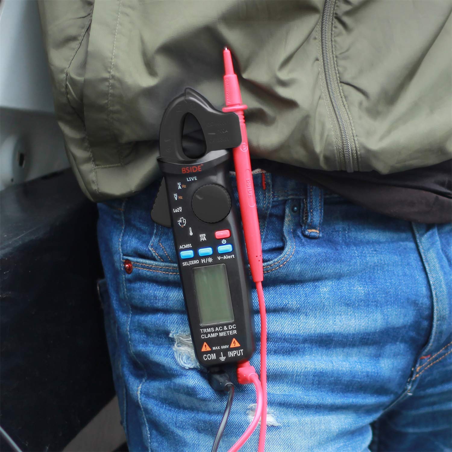
Figure 5.4: Performing a live wire check.
- Connect the red test lead to the INPUT terminal.
- Rotate the switch to the LIVE position.
- Insert the tip of the red test lead into the suspected live terminal or touch the conductor.
- The meter will indicate if the wire is live.
5.11 Data Hold and Backlight
Press the SEL/ZERO H/* button briefly to hold the current reading on the display. Press it again to release. Press and hold the SEL/ZERO H/* button to turn the backlight on or off.
6. Maintenance
6.1 Cleaning
Wipe the meter casing with a damp cloth and mild detergent. Do not use abrasives or solvents. Ensure the meter is completely dry before use.
6.2 Battery Replacement
When the low battery indicator appears on the display, replace the batteries promptly to ensure accurate readings. Refer to Section 4.1 for battery installation instructions.
6.3 Storage
If the meter is not used for an extended period, remove the batteries to prevent leakage. Store the meter in a cool, dry place, away from direct sunlight and extreme temperatures.
7. Troubleshooting
If you encounter issues with your BSIDE ACM91, refer to the following common problems and solutions:
- Meter does not power on: Check battery installation and ensure batteries are not depleted. Replace if necessary.
- Inaccurate readings (especially DC current): Ensure the zero function is used before DC current measurement. Reset the meter by turning it off and on. Ensure the conductor is centered within the clamp jaws.
- No reading or 'OL' (Overload) displayed: Check if the correct function is selected and if the measurement range is appropriate. Ensure test leads are properly connected and making good contact.
- Display is dim or flickering: Batteries may be low. Replace them.
- NCV not detecting voltage: Ensure the V~Alert button is pressed and the sensor area is close to the AC voltage source.
If the problem persists, contact customer support for assistance.
8. Technical Specifications
| Parameter | Specification |
|---|---|
| Display | 6000 Counts |
| DC Current (Clamp) | 6A/60A/100A, Resolution: 0.001A/0.01A/0.1A, Accuracy: ±(2.5%+5) |
| DC Current (µA via leads) | 0-200µA, Resolution: 0.1µA, Accuracy: ±(0.8%+5) |
| AC Current (Clamp) | 6A/60A/100A, Resolution: 0.001A/0.01A/0.1A, Accuracy: ±(2.5%+5) |
| DC Voltage | 6V/60V/600V, Resolution: 0.001V/0.01V/0.1V, Accuracy: ±(1.0%+3) |
| AC Voltage | 6V/60V/600V, Resolution: 0.001V/0.01V/0.1V, Accuracy: ±(1.0%+3) |
| Low Impedance (LOZ) Voltage | Max 600V, Resolution: 0.1V |
| Resistance | 0-60 MΩ, Resolution: 0.1 Ω, Accuracy: ±(1.0%+3) |
| Capacitance | 600µF/6000µF, Resolution: 0.1µF/1µF, Accuracy: ±(4%+3) |
| Frequency (via leads) | 45 Hz ~ 1000 Hz, 60Hz/1000Hz, Resolution: 0.1Hz/1Hz, Accuracy: ±(1.0%+5) |
| Frequency (via jaws) | 60Hz/1000Hz, Resolution: 0.1Hz/1Hz, Accuracy: ±(1.0%+5) |
| Temperature | -20 ℃ ~ 500 ℃ / -4 ℉ ~ 932 ℉, Resolution: 1 ℃/2 ℉, Accuracy: ±(2%+2) |
| NCV Detection | Up to 1000V with buzzer indication |
| Continuity | Buzzer sounds if resistance < 30 Ω |
| Jaw Opening | 20 mm |
| Power Supply | 2 x 1.5V AAA Batteries |
| Product Dimensions (L x W x H) | 17.9 x 6.7 x 3.6 cm |
| Item Weight | 137 Grams |
| Compliant Specifications | CE, IEC-61010-1, IEC-61010-2-030, IEC-61010-2-032, IEC-61010-2-033 |
9. Package Contents
The BSIDE ACM91 Digital Clamp Meter package includes the following items:
Figure 9.1: All items included in the BSIDE ACM91 package.
- BSIDE ACM91 Digital Clamp Meter
- Test Leads (one red, one black)
- 2 x AAA Batteries
- Carrying Case
- Screwdriver
- User Manual (English)
10. Warranty and Support
For warranty information and technical support, please refer to the documentation provided with your purchase or contact the seller directly. Keep your purchase receipt as proof of purchase for any warranty claims.


