
1. Introduction
Thank you for choosing the Garen PE01G-G Graphite Electronic Intercom. This manual provides essential information for the proper installation, operation, and maintenance of your new intercom system. Please read this manual thoroughly before installation and keep it for future reference.
2. Safety Instructions
- Ensure all electrical connections are made by a qualified professional and comply with local electrical codes.
- Disconnect power before performing any installation, maintenance, or repair work.
- Do not expose the outdoor unit to direct water jets or extreme weather conditions beyond its IP rating.
- Keep the device away from heat sources and direct sunlight to prevent damage.
- Do not attempt to disassemble or repair the unit yourself. Contact qualified service personnel.
- Use only original accessories and spare parts provided or approved by Garen.
3. Package Contents
Please check the package contents carefully. If any items are missing or damaged, contact your supplier immediately.
- 1 x Garen PE01G-G Outdoor Unit (Graphite)
- 1 x Garen Indoor Unit (Handset)
- Mounting Screws and Wall Plugs
- User Manual (this document)
4. Product Overview
Familiarize yourself with the components of your Garen PE01G-G Electronic Intercom system.
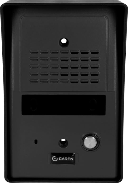
Figure 4.1: Outdoor Unit Front View. This image displays the front of the Garen PE01G-G outdoor intercom unit. It features a speaker grille at the top, a microphone opening, and a prominent call button at the bottom, along with the Garen logo. The unit is designed for external installation and is finished in a dark graphite color.

Figure 4.2: Outdoor Unit Rear View. This image shows the back of the Garen PE01G-G outdoor intercom unit. It highlights the mounting holes for secure installation and the wiring harness with colored wires (red, yellow, blue, green) for connecting to the indoor unit and power supply. The design includes structural ribs for rigidity.

Figure 4.3: Indoor Handset and Outdoor Unit. This image presents both the indoor handset (left, white) and the outdoor unit (right, graphite) of the Garen PE01G-G intercom system. The indoor unit features a cradle for the handset, a speaker, and a call button. The outdoor unit is shown with its receiver and speaker components. A coiled cord connects the indoor handset to its base.
5. Setup and Installation
Proper installation is crucial for the optimal performance of your intercom system. It is highly recommended that installation be performed by a qualified technician.
5.1. Outdoor Unit Installation
- Choose a suitable location near the entrance, protected from direct rain and sunlight if possible, at a height accessible to visitors.
- Mark the drilling points using the outdoor unit as a template.
- Drill holes and insert wall plugs.
- Route the necessary wiring (power, audio, and gate release if applicable) from the indoor unit location to the outdoor unit location.
- Connect the wires to the terminals on the back of the outdoor unit according to the wiring diagram provided in the product packaging (refer to Figure 4.2 for wire harness).
- Secure the outdoor unit to the wall using the provided screws.
5.2. Indoor Unit Installation
- Select a convenient indoor location, typically near the main entrance or a central area.
- Mark the drilling points for the indoor unit's mounting bracket.
- Drill holes, insert wall plugs, and secure the mounting bracket.
- Connect the wires from the outdoor unit and power supply to the indoor unit's terminals. Ensure correct polarity.
- Mount the indoor unit onto its bracket.
5.3. Power Connection
Connect the power supply to the indoor unit as per the wiring diagram. Ensure the power source matches the unit's voltage requirements. Do not apply power until all connections are secure and verified.
6. Operating Instructions
6.1. Receiving a Call
- When a visitor presses the call button on the outdoor unit, the indoor unit will ring.
- Lift the handset of the indoor unit to answer the call and communicate with the visitor.
6.2. Opening the Gate/Door
If your system is connected to an electric lock or gate opener, you can release it from the indoor unit.
- During a conversation, press the designated gate/door release button on the indoor unit (if available).
- The lock will momentarily activate, allowing the visitor to enter.
6.3. Ending a Call
Place the handset back into its cradle on the indoor unit to end the conversation.
7. Maintenance
- Cleaning: Use a soft, dry cloth to clean the surfaces of both indoor and outdoor units. For stubborn dirt, a slightly damp cloth can be used, followed by a dry cloth. Do not use abrasive cleaners, solvents, or strong chemicals.
- Inspection: Periodically check the outdoor unit for any signs of damage or wear, especially to the call button and speaker grille.
- Wiring: Ensure all wiring connections remain secure and free from corrosion.
8. Troubleshooting
| Problem | Possible Cause | Solution |
|---|---|---|
| No sound from outdoor unit speaker. | Loose wiring connection; Speaker damage. | Check wiring connections at both units. If problem persists, contact technical support. |
| Indoor unit does not ring when call button is pressed. | No power to indoor unit; Faulty call button; Wiring issue. | Verify power supply to the indoor unit. Check wiring connections. Test the call button. |
| Gate/door release not working. | Incorrect wiring to electric lock; Faulty release button; Lock malfunction. | Check wiring to the electric lock/gate opener. Ensure the lock itself is functional. |
| Poor audio quality (static, low volume). | Interference; Loose connections; Damaged microphone/speaker. | Check all wiring connections. Ensure no strong electrical interference sources nearby. |
If the problem persists after attempting these solutions, please contact Garen customer support or a qualified technician.
9. Specifications
| Feature | Detail |
|---|---|
| Model | PE01G-G |
| Brand | GAREN |
| Color | Graphite (Outdoor Unit) |
| Type | Electronic Intercom / Door Phone |
| ASIN | B0CB1K4DRY |
| EAN | 7899642382246 |
| Manufacturer | GAREN |
| Availability Date | January 6, 2024 |
10. Warranty and Support
Garen products are manufactured to high-quality standards and are covered by a manufacturer's warranty against defects in materials and workmanship. The specific warranty period and terms may vary by region and product. Please refer to the warranty card included with your product or visit the official Garen website for detailed warranty information.
For technical support, troubleshooting assistance, or warranty claims, please contact Garen customer service through the contact information provided on your product packaging or the official Garen website. Have your product model (PE01G-G) and purchase details ready when contacting support.
Extended warranty options may be available for purchase. Please check with your retailer or Garen for more details.