
1. Introduction
This manual provides detailed instructions for the installation, operation, and programming of the fushionsea AK-C211008 4-Channel Wireless Remote Control Switch. This device is designed for various control applications, including garage doors, industrial equipment, and household appliances, offering reliable wireless control.

Figure 1: The fushionsea AK-C211008 Wireless Remote Control Switch kit, including the receiver module, antenna, and orange 4-button remote control.
2. Product Components
The package includes the following items:
- 1 x Receiver Module (Model: AK-C211008)
- 1 x Transmitter (Orange 4-button remote control)
- 1 x 3-meter Cable Antenna
3. Specifications
3.1 Receiver (Model: AK-C211008)
- Working Voltage: DC12V-36V
- Quiescent Current: Less than 6mA
- Working Temperature: -40°C to +80°C
- Receiver Sensitivity: More than -105dBm
- Working Frequency: 433MHz
- Output Voltage: DC and AC (optional)
- Max Load Current: 10A
- Dimensions: 96mm x 80mm x 29mm

Figure 2: Internal view of the receiver module, showing the circuit board and relay components.
3.2 Transmitter (Orange 4-button remote control)
- Buttons: 4 Buttons (A, B, C, D)
- Working Voltage: DC9V (1PC 6F22 battery)
- Operating Frequency: 433MHz
- Remote Distance: 50-200 meters (open area)
- Operating Current: 13 mAh
- Encode: EV1527 code
- Dimensions: 150mm x 49mm x 31mm

Figure 3: The orange 4-button remote control, showing its physical dimensions.
4. Setup and Wiring
Proper wiring is crucial for the safe and correct operation of the remote control switch. Ensure all connections are secure and match the intended application.
4.1 Output 12-36V Voltage Wiring Diagram

Figure 4: Wiring diagram illustrating connections for 12-36V output voltage applications. Connect the input power (12-36V DC) to the designated terminals. The output terminals (NO, NC, COM) are used to control external devices.
4.2 Output Switch Signal Wiring Diagram

Figure 5: Wiring diagram for output switch signal applications. This configuration is typically used for controlling devices that require a dry contact closure or opening, such as gate openers or alarm systems.
4.3 Wiring Diagram for DC Motor Control
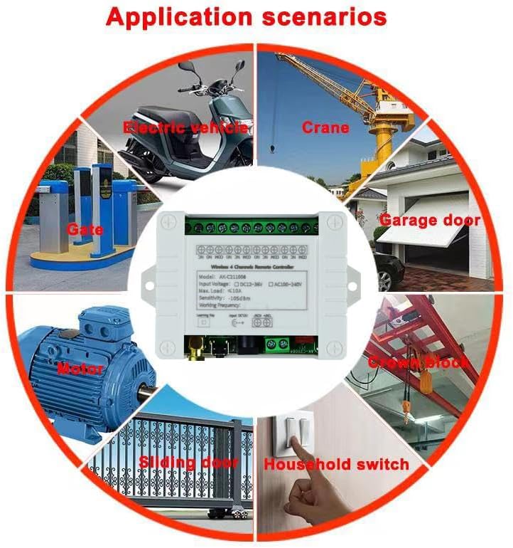
Figure 6: Wiring diagram for controlling a DC motor. This setup allows for directional control or on/off functionality of a DC motor using the relay outputs.
5. Operating Modes
The receiver supports six distinct operating modes, which can be configured using the learning button. The working way is changed by pressing the Learning Button a specific number of times.
- Momentary Mode (Press Learning Button 1 time):
Relay operation: Press and hold a button on the remote to turn the relay ON; release the button to turn the relay OFF. - Toggle Mode (Press Learning Button 2 times):
Relay operation: Press a button on the remote to turn the relay ON; press the same button again to turn the relay OFF. - Latched Mode (Press Learning Button 3 times):
Relay operation: Press a button on the remote to turn the relay ON; press another button on the remote to turn the relay OFF. - 2-Channel Momentary + 2-Channel Latched (Press Learning Button 4 times):
Channels 1 and 2 operate in Momentary mode, while Channels 3 and 4 operate in Latched mode. - 2-Channel Momentary + 2-Channel Toggle (Press Learning Button 5 times):
Channels 1 and 2 operate in Momentary mode, while Channels 3 and 4 operate in Toggle mode. - 2-Channel Toggle + 2-Channel Latched (Press Learning Button 6 times):
Channels 1 and 2 operate in Toggle mode, while Channels 3 and 4 operate in Latched mode.
6. Learning and Clearing Method
6.1 Learning a Remote Control
- Press the learning button on the receiver module the desired number of times corresponding to the operating mode you wish to set (e.g., 1 time for Momentary, 2 times for Toggle, etc.).
- The indicator light on the receiver will flash and then turn OFF.
- Release your finger from the learning button.
- Press any button on the remote transmitter.
- The indicator light on the receiver will flash three times, indicating successful learning.
6.2 Clearing Learned Codes
- Press and hold the learning button on the receiver module for approximately 8 seconds.
- The indicator light will flash several times and then turn OFF.
- After clearing, pressing a button on the remote will not elicit a response from the relay, confirming that the codes have been successfully cleared.
Video 1: Demonstration of the fushionsea AK-C211008 remote control switch in operation, showing how to pair the remote and control connected lights.
7. Application Scenarios
The fushionsea AK-C211008 wireless remote control switch is versatile and can be integrated into various control systems due to its stable RF technology and multiple operating modes. Common applications include:
- Anti-theft alarm control systems
- Electric doors and gates
- Lifting equipment (e.g., cranes)
- LED lighting control
- Elevator control
- Electric curtains and roller shutters
- Garage door openers
- Motorcycle and vehicle control
- Access control systems
- General industrial and household control applications

Figure 7: Visual representation of diverse application scenarios for the wireless remote control switch, including garage doors, gates, motors, and household switches.
8. Troubleshooting
If you encounter issues with your fushionsea AK-C211008 remote control switch, consider the following:
- No Response from Receiver:
- Check power supply to the receiver (DC12V-36V).
- Ensure the remote control battery (DC9V, 6F22) is not depleted.
- Verify that the remote control is properly learned to the receiver. If not, follow the learning procedure in Section 6.1.
- Confirm the antenna is securely connected to the receiver.
- Limited Range:
- Ensure there are no significant obstacles (thick walls, metal structures) between the remote and the receiver.
- Check for sources of RF interference in the vicinity.
- Verify the antenna is positioned optimally for reception.
- Incorrect Operating Mode:
- Review Section 5 to confirm the desired operating mode.
- Clear all learned codes (Section 6.2) and re-learn the remote control, ensuring the learning button is pressed the correct number of times for the desired mode.
9. Maintenance
To ensure the longevity and optimal performance of your fushionsea AK-C211008 remote control switch, follow these general maintenance guidelines:
- Keep the receiver and remote control clean and free from dust and moisture.
- Avoid exposing the devices to extreme temperatures or direct sunlight for extended periods.
- Regularly check the remote control battery and replace it when necessary to prevent operational issues.
- Ensure all wiring connections remain secure and free from corrosion.
10. Warranty and Support
For warranty information or technical support, please refer to the product packaging or contact fushionsea customer service through your purchase platform. Please have your model number (AK-C211008) and purchase details ready when contacting support.