
Supermicro MBD-X10DRG-O+-CPU
Supermicro X10DRG-O+-CPU Motherboard User Manual
Model: MBD-X10DRG-O+-CPU
1. Introduction
This user manual provides comprehensive instructions for the installation, configuration, and maintenance of the Supermicro X10DRG-O+-CPU Motherboard. This motherboard is designed for high-performance computing environments, supporting dual Intel Xeon E5-2600 v3/v4 processors and extensive memory configurations.
Please read this manual thoroughly before beginning the installation process to ensure proper setup and operation.
2. Safety Information
Always observe the following safety precautions when handling the motherboard and other computer components:
- Ensure the power supply is disconnected from the wall outlet before installing or removing any components.
- Wear an anti-static wrist strap or frequently touch a grounded metal object to discharge static electricity.
- Handle the motherboard by its edges to avoid touching sensitive components.
- Keep the motherboard away from liquids and extreme temperatures.
- Refer to the safety guidelines provided with other components (CPU, RAM, etc.) for additional precautions.
3. Package Contents
Verify that all items are present in the package. If any item is missing or damaged, contact your vendor immediately.
- Supermicro X10DRG-O+-CPU Motherboard
- I/O Shield
- SATA Cables (quantity may vary)
- Quick Reference Guide
- Driver CD/DVD (or link to download drivers)
4. Motherboard Layout
Below is an overview of the Supermicro X10DRG-O+-CPU Motherboard, highlighting key components and connectors.
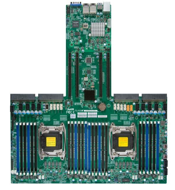
Figure 4.1: Supermicro X10DRG-O+-CPU Motherboard. This image displays the full motherboard, showing the dual CPU sockets, numerous DDR4 DIMM slots, PCIe expansion slots, and various I/O ports and connectors.
Key Components:
- CPU Sockets (LGA 2011-3): Two sockets for Intel Xeon E5-2600 v3/v4 processors.
- DDR4 DIMM Slots: Multiple slots supporting up to 3072 GB of ECC DDR4 memory.
- PCIe Expansion Slots: Various PCIe 3.0 slots for graphics cards, network cards, and other expansion devices.
- SATA Ports: Connectors for SATA 3.0 storage devices.
- USB Ports: USB 2.0 and USB 3.0 headers and rear panel ports.
- LAN Ports: Ethernet ports for network connectivity.
- Power Connectors: ATX 24-pin, 8-pin EPS, and 4-pin power connectors.
5. Setup
Follow these steps for proper installation of the motherboard and its components.
5.1 CPU Installation
- Open the CPU socket retention levers.
- Carefully align the CPU with the socket, ensuring the triangular mark on the CPU matches the mark on the socket.
- Gently place the CPU into the socket without forcing it.
- Close the retention levers to secure the CPU.
- Apply thermal paste and install the CPU cooler according to the cooler manufacturer's instructions.
5.2 Memory (RAM) Installation
- Open the clips at both ends of the DIMM slot.
- Align the notch on the DDR4 memory module with the key in the DIMM slot.
- Insert the module firmly into the slot until the clips snap into place.
- Repeat for all desired memory modules, following the motherboard's memory population guidelines for optimal performance.
5.3 Storage Device Installation
- Connect one end of the SATA data cable to a SATA port on the motherboard.
- Connect the other end of the SATA data cable to your SATA hard drive or SSD.
- Connect a SATA power cable from your power supply to the storage device.
5.4 Expansion Card Installation
- Select an appropriate PCIe slot for your expansion card (e.g., GPU, network card).
- Remove the corresponding slot cover from your PC case.
- Align the expansion card with the slot and press down firmly until it is fully seated.
- Secure the card with a screw or retention clip to the PC case.
5.5 Power Connections
- Connect the 24-pin ATX power connector from your power supply to the main power header on the motherboard.
- Connect the 8-pin EPS (CPU) power connector(s) to the corresponding headers near the CPU sockets.
- Ensure all power cables are securely connected.
5.6 Front Panel Connections
Connect the front panel cables (Power LED, HDD LED, Power Switch, Reset Switch, USB, Audio) from your PC case to the corresponding headers on the motherboard. Refer to the motherboard's silkscreen labels for correct pin assignments.
6. Operating
6.1 BIOS/UEFI Setup
Upon first boot, you may need to enter the BIOS/UEFI setup utility to configure system settings. Typically, you can access this by pressing DEL or F2 during the POST (Power-On Self-Test) sequence. Common settings to configure include boot order, date/time, and enabling/disabling specific features.
6.2 Driver Installation
After installing your operating system, install the necessary drivers for the motherboard's chipsets, LAN, audio, and other integrated components. Drivers can be found on the included driver CD/DVD or downloaded from the Supermicro official website.
6.3 Operating System Installation
Insert your operating system installation media (USB drive or DVD) and follow the on-screen prompts to install the OS. Ensure the boot order in BIOS/UEFI is set to prioritize your installation media.
7. Maintenance
7.1 Cleaning
Regularly clean dust from the motherboard and components using compressed air. Ensure the system is powered off and unplugged before cleaning. Avoid using liquids or abrasive materials.
7.2 Firmware Updates
Periodically check the Supermicro website for updated BIOS/UEFI firmware. Firmware updates can improve stability, performance, and add support for new hardware. Follow the provided instructions carefully when performing a firmware update to avoid system damage.
8. Troubleshooting
This section provides solutions to common issues you might encounter.
| Problem | Possible Cause | Solution |
|---|---|---|
| System does not power on. | Loose power cables, faulty power supply, incorrect front panel connections. | Check all power connections (24-pin, 8-pin EPS). Verify front panel power switch connection. Test power supply. |
| No display output. | Incorrectly seated GPU, faulty monitor cable, no integrated graphics. | Reseat the graphics card. Check monitor cable connections. Ensure monitor is on correct input. |
| System beeps repeatedly. | Memory (RAM) issue. | Reseat RAM modules. Try one module at a time. Refer to BIOS beep codes for specific diagnosis. |
| Operating system not found. | Incorrect boot order, loose SATA cable, unformatted drive. | Check BIOS/UEFI boot order. Reseat SATA cables. Ensure drive is properly formatted and OS installed. |
9. Specifications
Detailed technical specifications for the Supermicro X10DRG-O+-CPU Motherboard.
- Model Number: MBD-X10DRG-O+-CPU
- Brand: Supermicro
- CPU Support: Dual Intel Xeon E5-2600 v3/v4 Processors (LGA 2011-3)
- RAM Memory Maximum Size: 3072 GB DDR4 ECC
- System Bus Standard Supported: SATA 3
- S/PDIF Connector Type: Optical
- Package Dimensions: 25 x 25 x 4 inches
- UPC: 672042176427
- Date First Available: June 21, 2023
10. Warranty and Support
For warranty information and technical support, please refer to the official Supermicro website or contact your point of purchase. Keep your proof of purchase for warranty claims.
Supermicro Official Website: www.supermicro.com
Ask a question about this manual
Ask about setup, troubleshooting, compatibility, parts, safety, or missing instructions. Manuals+ will review the question and use this page’s manual context to help answer it.