Introduction
The Cleiscry SP902E is a versatile SPI signal amplifier and repeater designed to extend and strengthen signals for addressable LED pixel strips and panels, such as those using WS2812, WS2811, and WS2813 ICs. It supports both TTL and RS485 signal inputs and provides strong-drive TTL signal outputs, enabling reliable long-distance signal transmission and control for complex lighting setups.

Figure 1: Front view of the SP902E Signal Amplifier, highlighting input/output ports and specifications printed on the device.
Key Features
- Compatible with both TTL and RS485 signal inputs.
- Two channels of strong-drive TTL signal output for multiple strong signal control of lighting.
- Differential RS485 signal for cascading between amplifiers to achieve long-distance signal transmission.
- Can be used alone or in cascade with multiple units.
- Supports wide voltage input from DC5V to 24V, with reverse connection protection.
Product Specifications
| Model Number | SP902E |
| Voltage Input | DC 5-24V |
| Syn Signal | 5V TTL & DIFF |
| DAT Signal | 5V TTL |
| Rated Current | 10A |
| Working Temperature | -10℃ to 60℃ |
Setup and Wiring Instructions
Proper wiring is crucial for the correct operation of the SP902E signal amplifier. Refer to the diagrams below for typical connection scenarios.
Port Descriptions:
- Power Input Port (VCC, GND): Connect VCC to the positive terminal of the power supply and GND to the negative terminal. Supports DC5-24V.
- Cascading Signal Input and Output Port (IN+, IN-, OUT+, OUT-): Compatible with both TTL and RS485 signal inputs.
- IN+/IN-: Cascading signal input port. When connecting to the main controller, DAT of the main controller is connected to "IN+" and GND is connected to "IN-".
- OUT+/OUT-: Cascading signal output port. "OUT+" and "OUT-" are respectively connected to "IN+" and "IN-" of the next sub-amplifier.
- Export to LED (VCC, DAT, GND): Signal output for the connected LED strips/pixels.
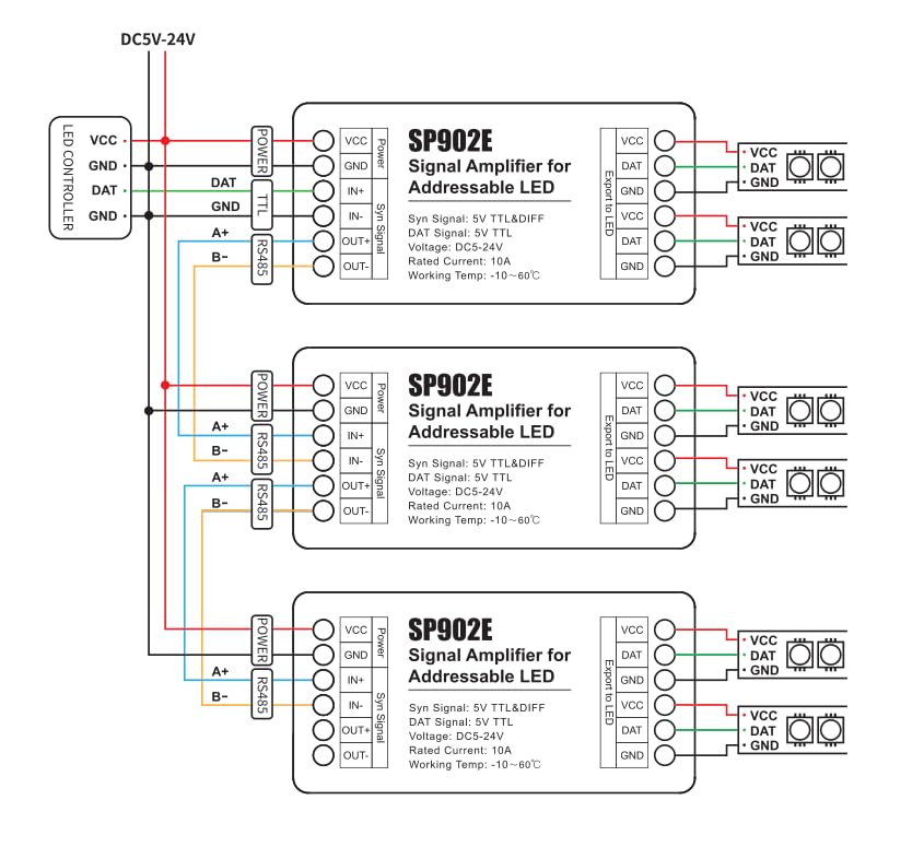
Figure 2: Typical wiring diagram for the SP902E signal amplifier, illustrating connections from an LED controller to multiple cascaded amplifiers and LED strips. This diagram shows power, TTL, and RS485 connections.

Figure 3: Detailed wiring instructions and port descriptions for the SP902E signal amplifier, including power, cascading signal input/output, and LED output.
Operation
Once properly wired, the SP902E signal amplifier operates automatically to strengthen and repeat the incoming SPI signal. It does not require any manual configuration or programming. Ensure that the input signal from your LED controller is compatible with the SP902E (5V TTL or RS485). The amplifier will then output a strong 5V TTL signal to the connected LED strips.
- Single Unit Use: Connect the LED controller's data and ground lines to the IN+ and IN- ports, respectively. Connect the LED strip's data, VCC, and GND to the amplifier's DAT, VCC, and GND output ports.
- Cascading Multiple Units: For longer distances or more LED strips, multiple SP902E units can be cascaded. Connect the OUT+ and OUT- of the preceding amplifier to the IN+ and IN- of the next amplifier in the chain. Each amplifier should be powered independently or from a common power supply capable of handling the total current.
Maintenance
The SP902E signal amplifier is designed for low maintenance. Keep the device in a dry environment, away from direct sunlight and extreme temperatures. Ensure all connections are secure and free from corrosion. Periodically check for any loose wiring, especially in installations subject to vibration.
Troubleshooting
- LEDs not lighting up or flickering:
- Check all power connections (VCC, GND) to ensure they are secure and providing the correct voltage (DC 5-24V).
- Verify the input signal from the LED controller is correctly connected to IN+ and IN-.
- Ensure the output signal from the amplifier is correctly connected to the LED strip's data, VCC, and GND.
- Confirm the LED strip itself is functional by testing it with a known working controller or directly.
- If cascading, check connections between all amplifiers in the chain.
- Signal degradation over long distances:
- Ensure you are using shielded twisted pair or CAT5/CAT6 Ethernet cables for long-distance RS485 signal transmission.
- Verify that the number of cascaded amplifiers is appropriate for the total distance and environment.
- Amplifier overheating:
- The current passed by the amplifier is limited to 10A. If the LED lighting requires more current, additional power supplies must be used for the LED strips to prevent overloading the amplifier.
- Ensure adequate ventilation around the amplifier.
- Incorrect colors or patterns:
- This is typically an issue with the LED controller's programming or settings, not the amplifier. Ensure your controller is configured for the correct LED chip type (e.g., WS2812, WS2811, WS2813).
Important Precautions
- The current capacity of the amplifier is limited. If the connected LED lighting requires a current exceeding 10A, additional power supplies must be used for the LED strips to prevent overheating and potential damage to the amplifier.
- The strength of the TTL signal output by the amplifier is related to the type of chip used in the connected LEDs, the length and thickness of the connecting wires, and the number of LEDs connected in parallel. Use within a reasonable range according to the actual situation.
- The transmission distance between amplifiers is affected by the type of wire used and the surrounding environment. For long-distance signal transmission or in complex environments with significant interference, use shielded twisted pair or CAT5/CAT6 Ethernet cables.
- Ensure correct polarity when connecting power. The device includes reverse connection protection, but incorrect wiring can still lead to issues.
- Do not expose the device to moisture or extreme temperatures.
Warranty and Support
For warranty information or technical support, please refer to the product packaging or contact your retailer. Keep your purchase receipt for warranty claims.
