1. Introduction
This manual provides comprehensive instructions for the GOWENIC H110B4 H110 Computer Motherboard. It is designed to assist users in the proper installation, configuration, and maintenance of the motherboard, ensuring reliable and efficient operation of your computer system. Please read this manual thoroughly before proceeding with any installation or setup procedures.
2. Product Overview
The GOWENIC H110B4 H110 Motherboard is designed for desktop and server applications, supporting LGA1151 pin CPUs such as Intel Core i5-6500 and i7-6700. It features DDR4 memory support and an M.2 interface for high-speed storage.
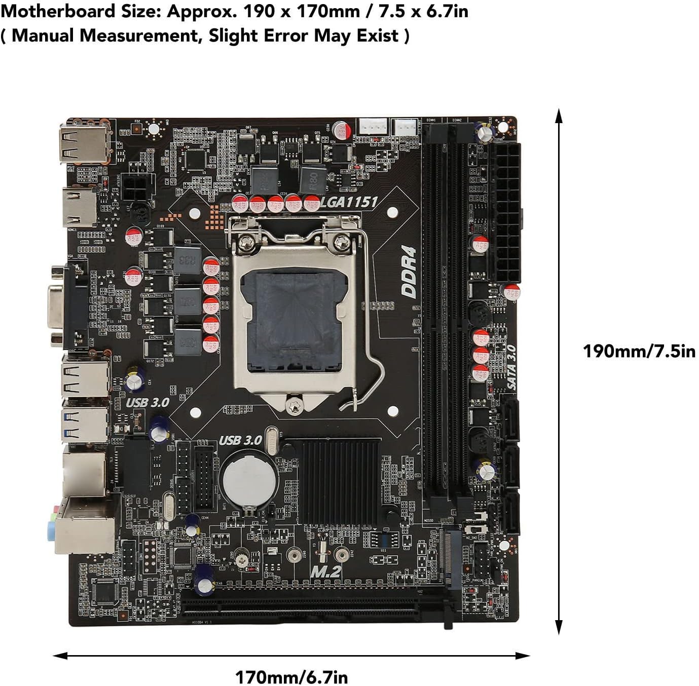
Figure 2.1: GOWENIC H110B4 H110 Motherboard with approximate dimensions (190 x 170mm / 7.5 x 6.7in).
Video 2.1: Overview of the GOWENIC H110B4 H110 Computer Motherboard, showcasing its physical appearance and various angles.
3. Key Features
- Easy Expansion: Equipped with HD Multimedia Interface and VGA interface. The M.2 interface supports both NGFF and NVME protocols.
- SATA3.0 Interface: Features SATA3.0 ports for strong compatibility and fast data transfer speeds.
- High-Speed M.2: The M.2 hard disk interface supports speeds up to 32GB/s.
- All Solid-State Capacitance: Utilizes solid-state capacitors for stable performance and extended motherboard lifespan.
- DDR4 SO DIMM: Supports dual-channel DDR4 SO DIMM memory, with a maximum capacity of 64GB.
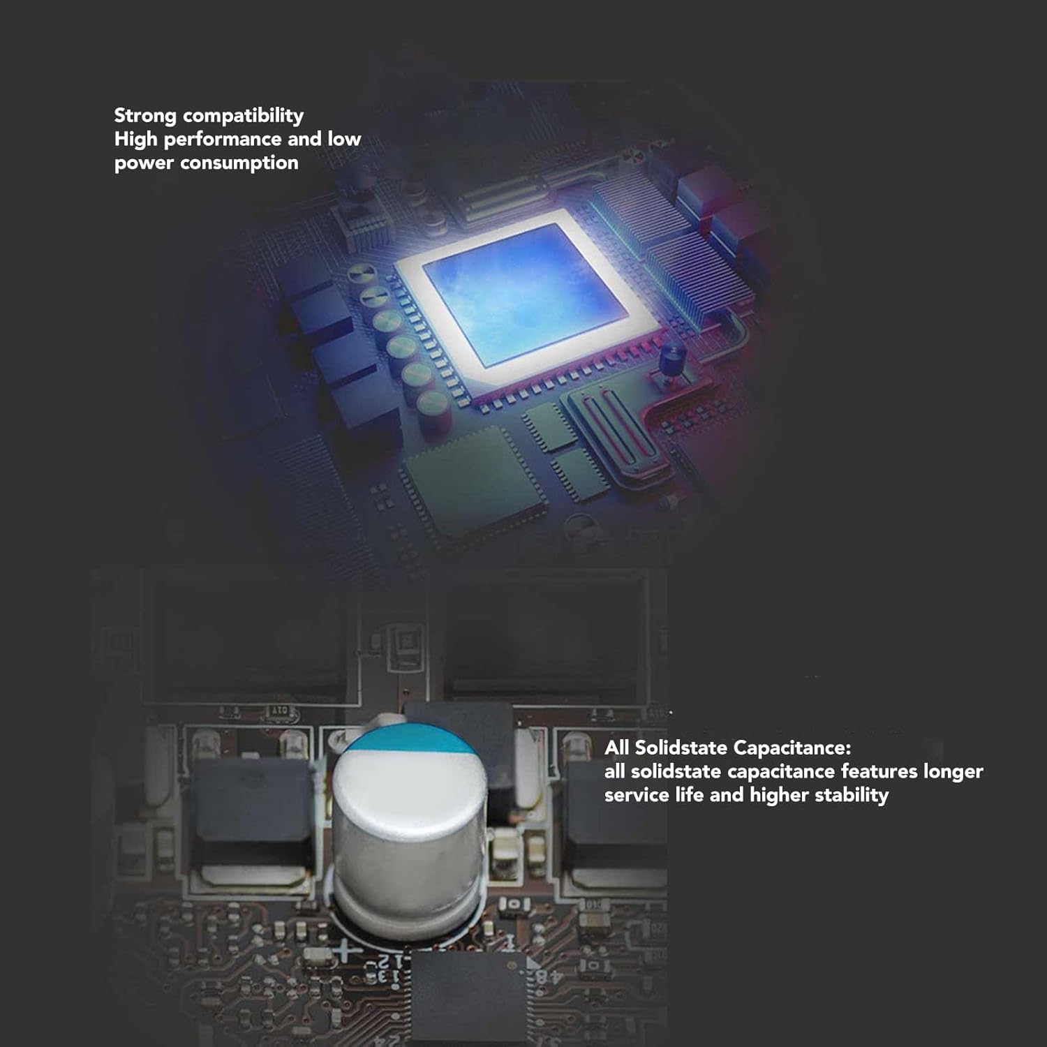
Figure 3.1: Close-up view of the solid-state capacitors, highlighting their design for enhanced stability and durability.
4. Motherboard Interface Layout
Understanding the layout of the motherboard interfaces is crucial for proper component installation. Refer to the diagram below for a detailed view of all ports and connectors.
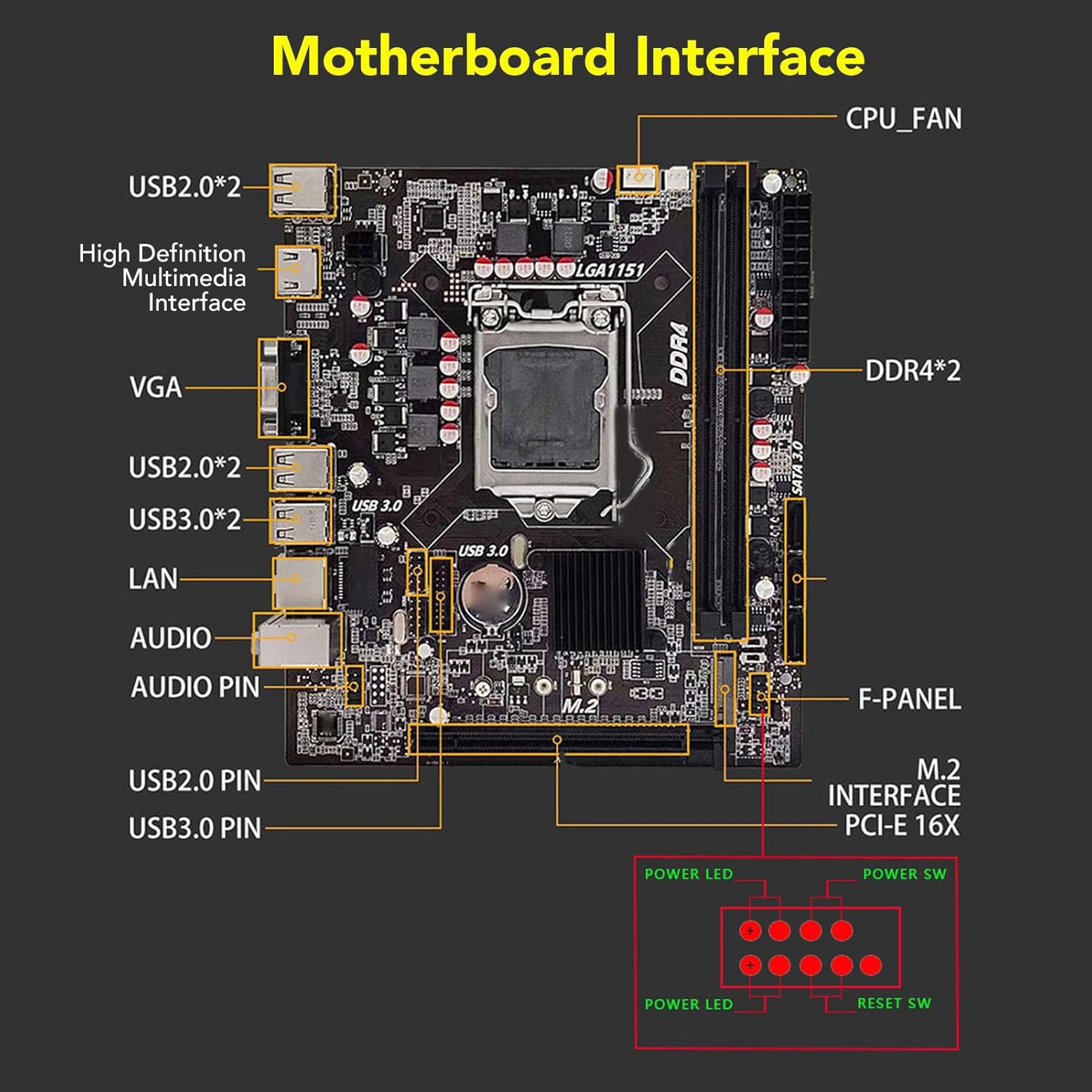
Figure 4.1: Detailed diagram illustrating the various interfaces on the GOWENIC H110B4 H110 Motherboard, including USB ports, video outputs, audio jacks, LAN, CPU fan header, DDR4 slots, SATA 3.0 ports, M.2 interface, and front panel connectors.
- CPU_FAN: CPU Fan Header
- DDR4*2: Two DDR4 SO DIMM memory slots
- SATA 3.0: SATA 3.0 ports for storage devices
- M.2 Interface PCI-E 16X: M.2 slot for NVMe/NGFF SSDs and PCI-E x16 slot
- F-PANEL: Front Panel Header (Power LED, Power SW, Reset SW)
- USB3.0 PIN / USB2.0 PIN: Internal USB headers
- AUDIO / AUDIO PIN: Audio jacks and internal audio header
- LAN: Ethernet port
- USB3.0*2 / USB2.0*2: External USB 3.0 and USB 2.0 ports
- VGA / High Definition Multimedia Interface: Video output ports
5. Setup and Installation
5.1 CPU Installation
Follow these steps carefully to install your LGA1151 CPU onto the motherboard. Ensure proper alignment to prevent damage to the CPU or socket pins.
- Open CPU Socket: Press down the wire buckle on the CPU socket and lift it upward. Do not remove the black protective cover before installing the CPU.
- Align CPU: Observe the three bayonets (alignment notches) in the motherboard's CPU socket and the corresponding three bayonets on the CPU itself (often marked with a red circle in diagrams). Align the left side of the CPU with the socket and gently place it down.
- Verify Placement: Ensure the CPU is seated correctly and evenly within the socket.
- Secure CPU: Carefully put the wire buckle back down. At this point, the black protective cover will automatically eject. Remember not to manually remove the black cover before installing the CPU.

Figure 5.1: Visual guide for installing an LGA1151 CPU, showing the process of opening the socket, aligning the CPU, and securing it.
5.2 RAM (DDR4 SO DIMM) Installation
The motherboard supports DDR4 SO DIMM memory modules.
- Open Latches: Gently push open the retention clips at both ends of the DDR4 memory slots.
- Align Module: Align the notch on the DDR4 SO DIMM module with the key in the memory slot.
- Insert Module: Press down firmly and evenly on both ends of the memory module until the retention clips snap into place, securing the module.
- Verify Installation: Ensure the module is fully seated and the clips are locked.
5.3 Storage Device Installation (M.2 and SATA)
The motherboard supports both M.2 NVMe/NGFF SSDs and traditional SATA 3.0 hard drives/SSDs.
M.2 SSD Installation:
- Locate M.2 Slot: Identify the M.2 slot on the motherboard.
- Insert SSD: Gently insert the M.2 SSD into the slot at a 30-degree angle, ensuring the notch aligns.
- Secure SSD: Push the SSD down and secure it with the provided screw.
SATA Device Installation:
- Connect SATA Cable: Connect one end of a SATA data cable to a SATA 3.0 port on the motherboard and the other end to your SATA hard drive or SSD.
- Connect Power: Connect a SATA power cable from your power supply unit (PSU) to the storage device.
5.4 Power Connections
Connect the main 24-pin ATX power connector and the 4-pin or 8-pin CPU power connector from your PSU to the corresponding ports on the motherboard.
5.5 Front Panel Connections
Connect the case's front panel cables (Power SW, Reset SW, Power LED, HDD LED, USB, Audio) to the corresponding headers on the motherboard as indicated in the Motherboard Interface Layout diagram (Figure 4.1). Pay close attention to polarity for LED connectors.
5.6 I/O Shield and SATA Cable
The motherboard package includes an I/O shield and a SATA data cable. The I/O shield is installed into your computer case before mounting the motherboard, providing protection and labeling for the rear ports. The SATA cable is used to connect storage devices.

Figure 5.2: The GOWENIC H110B4 H110 Motherboard shown alongside its included I/O shield and a SATA data cable.
6. Specifications
Below are the detailed technical specifications for the GOWENIC H110B4 H110 Motherboard.
| Feature | Specification |
|---|---|
| Brand | GOWENIC |
| Model Name | H110B4 (Item model number: GOWENIC6k9ep2zi7c) |
| CPU Socket | LGA 1151 |
| Compatible Processors | Intel Core i5-6500, Intel Core i7-6700 |
| Chipset Type | Intel H110 |
| RAM Memory Technology | DDR4 SO DIMM |
| Memory Clock Speed | 2133 MHz (Supports up to 64GB) |
| Storage Interface | SATA 3.0, M.2 (NGFF/NVME protocol, up to 32GB/s) |
| Video Output | HD Multimedia Interface, VGA |
| Compatible Devices | Personal Computer |
| Platform | Windows |
| Item Weight | 1.23 pounds |
| Package Dimensions | 10.94 x 10.12 x 2.28 inches |
7. Troubleshooting
If you encounter issues with your motherboard, consider the following common troubleshooting steps:
- No Power: Ensure all power cables (24-pin ATX, CPU power) are securely connected from the PSU to the motherboard. Check the power supply unit itself.
- No Display: Verify that the monitor is connected to the correct video output (HD Multimedia Interface or VGA) on the motherboard or discrete graphics card. Reseat RAM modules and the graphics card (if applicable).
- System Instability/Crashes: Check RAM modules for proper seating. Test with one RAM module at a time. Ensure CPU cooler is properly installed and making good contact. Update BIOS (if possible and necessary, with caution).
- Boot Device Not Found: Check SATA and M.2 connections for storage devices. Verify boot order in BIOS/UEFI settings.
- Peripheral Issues: Ensure USB and other peripheral cables are correctly connected to the motherboard headers and external ports.
8. Safety Information
Always observe the following safety precautions when handling computer components:
- Static Electricity: Always ground yourself before touching any components to prevent electrostatic discharge (ESD) damage. Use an anti-static wrist strap or touch a grounded metal object.
- Power Off: Ensure the computer is completely powered off and unplugged from the wall outlet before installing or removing any components.
- Handle with Care: Handle the motherboard and other components by their edges to avoid touching sensitive circuits.
- Ventilation: Ensure adequate ventilation within your computer case to prevent overheating.
9. Warranty and Support
For warranty information and technical support, please refer to the documentation provided with your purchase or visit the official GOWENIC website. Keep your proof of purchase for warranty claims.