1. Introduction
This manual provides comprehensive instructions for the Power Probe Professional Electrical Test Kit. This kit is designed for automotive electrical testing and repair, featuring the Power Probe 3, a Digital Multimeter, and an Auto AC Temperature Testing Kit. It is suitable for various automotive applications, including gas-powered, hybrid, and electric vehicles.
The kit includes:
- Power Probe 3 for diagnosing automotive circuit issues.
- Digital Multimeter for inspecting multiple electrical readings.
- Auto AC Temperature Testing Kit for evaluating vehicle AC system performance.
- Various accessories to support testing.

Figure 1.1: The complete Power Probe Professional Electrical Test Kit, including the Power Probe 3, Digital Multimeter, and Auto AC Temperature Testing Kit, neatly organized within its durable red carrying case.

Figure 1.2: An overview of the kit's contents, showing the Power Probe 3, Digital Multimeter, temperature sensors, various leads, clips, and probes, all arranged within the open carrying case.
2. Safety Information
Always observe the following safety precautions when using the Power Probe Professional Electrical Test Kit:
- Wear appropriate personal protective equipment, including safety glasses.
- Ensure the vehicle's ignition is off and the parking brake is engaged before performing electrical tests, unless specific instructions require otherwise.
- Avoid contact with live electrical circuits.
- Do not use the tools if they appear damaged.
- Refer to the vehicle manufacturer's service manual for specific electrical system diagrams and procedures.
- Keep children and unauthorized personnel away from the work area.
3. Setup
3.1. Power Probe 3
- Battery Installation: The Power Probe 3 is typically powered by the vehicle's battery. Connect the red lead to the positive (+) terminal and the black lead to the negative (-) terminal of the vehicle battery.
- Probe Tip Attachment: Ensure the probe tip is securely attached to the Power Probe 3 unit.
3.2. Digital Multimeter
- Battery Installation: Open the battery compartment (usually on the back) and insert the required batteries, observing polarity.
- Lead Connection: Connect the black test lead to the "COM" (common) jack. Connect the red test lead to the appropriate jack for the measurement type (e.g., "VΩmA" for voltage, resistance, or current).
3.3. Auto AC Temperature Testing Kit
- Battery Installation: Install batteries into the main display unit and each wireless temperature sensor, ensuring correct polarity.
- Sensor Placement: Place the wireless temperature sensors into the vehicle's AC vents or other desired measurement locations.
- Power On: Turn on the main display unit and each sensor. The display unit should automatically connect to the sensors.
4. Operating Instructions
4.1. Using the Power Probe 3
The Power Probe 3 is used to apply power or ground to components and test for voltage and continuity.
- Voltage Testing: Touch the probe tip to the circuit or component. The LCD screen will display the voltage. Red/Green lights indicate positive/negative polarity.
- Applying Power/Ground: Use the rocker switch to apply battery voltage or ground to a component for functional testing. Exercise caution to avoid short circuits.
- Continuity Testing: Connect the auxiliary ground lead to a known good ground. Touch the probe tip to the component. The LCD will indicate continuity.
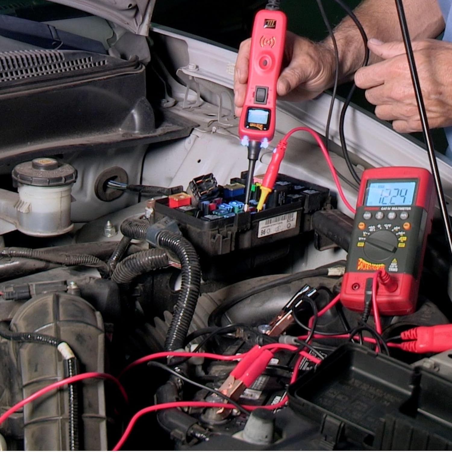
Figure 4.1: A Power Probe 3 being used to test an automotive fuse box. The probe tip is inserted into a fuse slot, and the LCD screen displays the voltage reading, while the red and black leads are connected to the vehicle's battery.
4.2. Using the Digital Multimeter
The Digital Multimeter can measure various electrical parameters.
- Voltage (DC/AC): Turn the rotary switch to the desired voltage range (DCV or ACV). Connect the test leads in parallel with the circuit or component.
- Resistance (Ω): Turn the rotary switch to the Ω (ohms) range. Ensure the circuit is de-energized. Connect the test leads across the component.
- Current (A): Turn the rotary switch to the desired current range (DCA or ACA). Connect the multimeter in series with the circuit. Caution: Incorrect connection can damage the multimeter or vehicle.
- Continuity: Turn the rotary switch to the continuity setting (often indicated by a speaker icon). A beep indicates continuity.
- Other Functions: Refer to the multimeter's specific markings for frequency, temperature, and capacitance measurements.

Figure 4.2: The Digital Multimeter displaying a voltage reading while connected to a car battery. The red and black test leads are attached to the positive and negative terminals of the battery, respectively.
4.3. Using the Auto AC Temperature Testing Kit
This kit provides wireless temperature readings to assess AC system performance.
- Sensor Placement: Insert the wireless temperature sensors into the vehicle's AC vents. The kit supports dual-zone readings.
- Monitoring Readings: The main display unit will show real-time temperature readings from the connected sensors.
- Range: Sensors can transmit readings from up to 16.5 feet away.

Figure 4.3: A wireless temperature sensor from the Auto AC Temperature Testing Kit inserted into a car's air conditioning vent, displaying a temperature reading on its screen.

Figure 4.4: The main display unit of the Auto AC Temperature Testing Kit positioned on a car dashboard, showing dual temperature readings. Two wireless sensors are visible, one placed in an AC vent and another held by a hand, demonstrating multi-point temperature monitoring.
5. Maintenance
- Cleaning: Wipe down all tools with a clean, dry cloth after each use. Do not use abrasive cleaners or solvents.
- Storage: Store the kit in its original carrying case in a dry, cool place, away from direct sunlight and extreme temperatures.
- Battery Replacement: Replace batteries in the Digital Multimeter and Auto AC Temperature Testing Kit components as needed. Refer to the individual component manuals for specific battery types and replacement procedures.
- Lead Inspection: Regularly inspect test leads and probes for signs of wear, cuts, or damage. Replace damaged leads immediately to ensure safety and accurate readings.
6. Troubleshooting
| Problem | Possible Cause | Solution |
|---|---|---|
| Power Probe 3 not powering on. | Incorrect connection to vehicle battery; vehicle battery is dead. | Ensure red lead is connected to positive (+) and black lead to negative (-) terminals. Check vehicle battery charge. |
| Multimeter displays "OL" or no reading. | Incorrect range selected; dead batteries; open circuit. | Select appropriate range. Replace multimeter batteries. Check for breaks in the circuit being tested. |
| AC Temp Kit sensors not connecting. | Dead sensor batteries; sensors out of range; interference. | Replace sensor batteries. Move sensors closer to the main unit. Reduce potential sources of wireless interference. |
| Inaccurate readings. | Damaged leads/probes; incorrect measurement technique; environmental factors. | Inspect and replace damaged leads. Review operating instructions for correct technique. Ensure stable testing environment. |
7. Specifications
- Brand: Power Probe
- Model: Power Probe 3-Piece Electrical and AC Auto Testing Kit
- Power Source: Battery Powered (for Multimeter and Temp Kit); Vehicle Battery Powered (for Power Probe 3)
- Measurement Type: Multimeter (Voltage, Resistance, Current, Continuity, Frequency, Temperature, Capacitance)
- Power Probe 3 Features: LCD screen, Red/Green polarity indicators, apply power/ground.
- AC Temp Kit Features: Wireless, dual-zone readings, up to 16.5 ft range.
- ASIN: B0C883M82M
- Date First Available: June 16, 2023
8. Warranty and Support
For warranty information and technical support, please refer to the documentation included with your purchase or visit the official Power Probe website. Keep your proof of purchase for warranty claims.
For additional assistance, you may contact Power Probe customer service through their official channels.


