1. Introduction
This manual provides detailed instructions for the safe and effective operation of your GVDA GD106B Digital Multimeter. This True RMS auto-ranging multimeter is designed for measuring DC/AC Voltage, DC/AC Current, Resistance, Capacitance, Diode, Continuity, NCV (Non-Contact Voltage), Live Wire detection, and Battery testing. Its compact design and comprehensive features make it an essential tool for electricians, hobbyists, and DIY enthusiasts.
2. Safety Information
Always observe safety precautions when using electrical testing equipment. Failure to do so may result in injury or damage to the meter or equipment under test.
- Do not exceed the maximum input values for any function.
- Use extreme caution when working with voltages above 30V AC RMS, 42V peak, or 60V DC. These voltages pose a shock hazard.
- Always disconnect power to the circuit and discharge all high-voltage capacitors before performing resistance, continuity, or diode tests.
- Inspect test leads for damaged insulation or exposed metal. Replace if damaged.
- Ensure the function switch is in the correct position for the desired measurement before connecting the test leads to the circuit.
- Do not operate the meter if it appears damaged or if the case is open.
- Remove test leads from the meter before opening the battery cover.
3. Product Overview and Components
Familiarize yourself with the main components of your GVDA GD106B Digital Multimeter.

Figure 3.1: Front view of the GVDA GD106B Digital Multimeter with its red and black test leads. The display shows "4000 Counts" and various measurement indicators. The rotary dial is set to OFF.
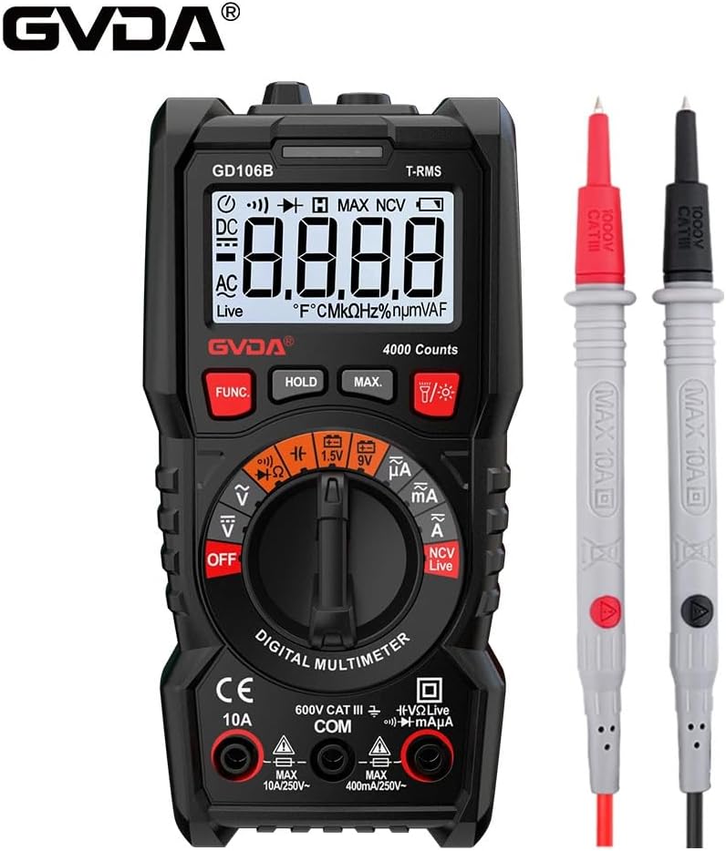
Figure 3.2: Another view of the GVDA GD106B Digital Multimeter, highlighting the GVDA brand logo at the top left. The meter is shown with its test leads.
Key Components:
- LCD Display: Shows measurement readings, units, and function indicators.
- Function Rotary Switch: Selects the desired measurement function.
- Function Buttons: (FUNC, HOLD, MAX, Light/Flashlight) For additional features and mode selection.
- Input Jacks:
- COM Jack: Common input for all measurements (negative lead).
- VΩmA Jack: Input for Voltage, Resistance, Capacitance, Diode, Continuity, and small Current (mA/µA) measurements (positive lead).
- 10A Jack: Input for large Current (A) measurements (positive lead).
- Test Leads: Red (positive) and Black (negative) leads for connecting to circuits.
4. Setup
4.1 Battery Installation
The GVDA GD106B Multimeter requires 2 x 1.5V AAA batteries (not included) for operation.
- Ensure the multimeter is turned OFF and disconnect all test leads from the input jacks.
- Locate the battery compartment cover on the back of the meter.
- Use a screwdriver to loosen the screw securing the battery cover.
- Remove the battery cover.
- Insert two 1.5V AAA batteries, observing the correct polarity (+ and -) as indicated inside the compartment.
- Replace the battery cover and tighten the screw.

Figure 4.1: Image showing the open battery compartment of the multimeter, indicating where to insert two 1.5V AAA batteries.
5. Operating Instructions
Before making any measurement, ensure the test leads are correctly inserted into the appropriate input jacks and the rotary switch is set to the desired function.
5.1 DC/AC Voltage Measurement
- Insert the red test lead into the VΩmA jack and the black test lead into the COM jack.
- Turn the rotary switch to the V~ (AC Voltage) or V- (DC Voltage) position. The meter will auto-range.
- Connect the test leads in parallel to the circuit or component you wish to measure.
- Read the voltage value on the LCD display.
5.2 DC/AC Current Measurement
- For currents up to 400mA, insert the red test lead into the VΩmA jack. For currents up to 10A, insert the red test lead into the 10A jack. Insert the black test lead into the COM jack.
- Turn the rotary switch to the mA~ (AC Current) or mA- (DC Current) position. Use the FUNC button to switch between AC and DC if needed.
- Disconnect power to the circuit. Open the circuit where you want to measure current.
- Connect the multimeter in series with the circuit.
- Apply power to the circuit and read the current value on the LCD display.
- Caution: Never connect the multimeter in parallel to a voltage source when measuring current, as this can blow the fuse or damage the meter.
5.3 Resistance Measurement
- Insert the red test lead into the VΩmA jack and the black test lead into the COM jack.
- Turn the rotary switch to the Ω position.
- Ensure the circuit or component is de-energized and discharged.
- Connect the test leads across the component to measure its resistance.
- Read the resistance value on the LCD display.
5.4 Capacitance Measurement
- Insert the red test lead into the VΩmA jack and the black test lead into the COM jack.
- Turn the rotary switch to the Capacitance position (often shared with Ω or Diode, use FUNC to select).
- Ensure the capacitor is fully discharged before testing.
- Connect the test leads across the capacitor terminals.
- Read the capacitance value on the LCD display.
5.5 Diode Test and Continuity Measurement
- Insert the red test lead into the VΩmA jack and the black test lead into the COM jack.
- Turn the rotary switch to the Diode/Continuity position. Use the FUNC button to toggle between Diode test and Continuity.
- Diode Test: Connect the red lead to the anode and the black lead to the cathode of the diode. The display will show the forward voltage drop. Reverse the leads; the display should show OL (Open Loop) for a good diode.
- Continuity Test: Connect the test leads across the circuit or component. If the resistance is below approximately 50Ω, the buzzer will sound, indicating continuity.
5.6 NCV (Non-Contact Voltage) Measurement
The NCV function allows you to detect AC voltage without direct contact with the conductor.
- Turn the rotary switch to the NCV position.
- Move the top tip of the multimeter close to the conductor or outlet.
- If AC voltage is detected, the meter will beep and the NCV indicator light will flash. The intensity of the beeping and flashing indicates the strength of the detected field.

Figure 5.1: Demonstrates the NCV (Non-Contact Voltage) measurement function, with the multimeter held near a wall outlet detecting an electrical field.
5.7 Live Wire Test
This function helps identify live wires in an AC circuit.
- Insert the red test lead into the VΩmA jack. The black lead is not needed for this test.
- Turn the rotary switch to the Live position.
- Touch the red test lead to the wire or terminal you suspect is live.
- If a live voltage is detected, the display will show "Live" and the meter will beep.

Figure 5.2: The multimeter is shown performing a live wire detection test by inserting the red test lead into a power strip socket.
5.8 Battery Test (1.5V/9V)
- Insert the red test lead into the VΩmA jack and the black test lead into the COM jack.
- Turn the rotary switch to the 1.5V or 9V battery test position.
- Connect the red test lead to the positive terminal of the battery and the black test lead to the negative terminal.
- Read the battery voltage on the display.
5.9 Special Functions
- Data Hold (HOLD button): Press to freeze the current reading on the display. Press again to release.
- Maximum Measurement (MAX button): Press to display the maximum value measured since the function was activated.
- Backlight/Flashlight (Light button): Press to turn on the display backlight. Long press to activate the built-in flashlight.
- True RMS: The meter provides True RMS measurements for AC voltage and current, ensuring accurate readings for non-sinusoidal waveforms.
- Auto Range: The meter automatically selects the appropriate measurement range, simplifying operation.
6. Maintenance
6.1 Cleaning
Wipe the case with a damp cloth and mild detergent. Do not use abrasives or solvents. Keep the input terminals free of dirt and moisture.
6.2 Battery Replacement
When the "Low Battery Indication" icon appears on the display, replace the batteries as described in Section 4.1. Prompt battery replacement ensures accurate readings and proper operation.
6.3 Auto Power Off
To conserve battery life, the multimeter will automatically power off after a period of inactivity. Press any button or turn the rotary switch to wake it up.
7. Troubleshooting
| Problem | Possible Cause | Solution |
|---|---|---|
| Meter does not power on. | Dead or incorrectly installed batteries. | Check battery polarity or replace batteries. |
| "OL" (Overload) displayed. | Measurement exceeds selected range or meter's maximum input. | Ensure the correct function is selected. For auto-ranging, this indicates the value is beyond the meter's capability. |
| Incorrect readings. | Incorrect function selected, poor test lead connection, or low battery. | Verify function switch position. Check test lead connections. Replace batteries if low battery indicator is on. |
| No continuity beep. | Circuit resistance is too high, or continuity function not selected. | Ensure continuity mode is active (use FUNC button). Check if the circuit is truly continuous. |
8. Specifications
| Parameter | Value |
|---|---|
| DC Voltage | 400mV/4V/40V/400V/600V (±0.5%+3) |
| AC Voltage | 4V/40V/400V/600V (±1.0%+3) |
| DC Current | 400uA/4000uA/40mA/400mA/4A/10A (±1.2%+3) |
| AC Current | 400uA/4000uA/40mA/400mA/4A/10A (±1.5%+3) |
| Resistance | 400Ω/4kΩ/40kΩ/400kΩ (±1.0%+3); 4MΩ/40MΩ (±1.2%+3) |
| Capacitance | 4nF/40nF/400nF/4µF/40µF/400µF/4mF (±4.0%+5) |
| Fuse Protection | F400mA/250V fuse; F10A/250V fuse |
| Counts | 4000 Counts |
| Live Wire Test | Yes |
| NCV Measurement | Yes |
| Battery Test | 1.5V/9V |
| Diode Test | Yes |
| Continuity Measurement | Yes |
| Maximum Measurement | Yes |
| Data Hold | Yes |
| True RMS | Yes |
| Low Battery Indication | Yes |
| Auto Power Off | Yes |
| Backlight | Yes |
| Flashlight | Yes |
| Auto Range | Yes |
| Power Supply | 2x 1.5V AAA Batteries (not included) |
| Product Size | 151mm x 75mm x 46mm |
| Product Weight | 207g |
8.1 Package Contents

Figure 8.1: The complete package contents, including the GVDA GD106B Digital Multimeter, test leads, user manual, and gift box.
- 1 PC Digital Multimeter (GD106B)
- 1 PC User Manual
- 1 PC Test Pen (Test Leads)
- 1 PC Gift Box
9. Warranty and Support
Specific warranty information for the GVDA GD106B Digital Multimeter is not provided in the product description. Please refer to the seller or manufacturer's official website for warranty details and customer support contact information.
For technical assistance or inquiries, please contact your point of purchase or the GVDA customer service department.


