1. Introduction
This manual provides detailed instructions for the safe and effective operation of the GVDA GD166B True RMS Digital Clamp Meter. This high-performance smart digital clamp meter is designed to simplify and enhance your electrical measurement tasks. It integrates a wide range of functions, making it an essential tool for professionals and enthusiasts alike.
The GD166B is capable of measuring AC/DC voltage, AC/DC current, frequency, duty cycle, resistance, capacitance, temperature, diode, continuity, NCV (Non-Contact Voltage) detection, live wire detection, and more.
2. Safety Information
WARNING: To avoid electric shock or personal injury, read and understand all safety information before using this product.
- Always adhere to local and national safety codes.
- Do not use the meter if it appears damaged or if the insulation is compromised.
- Do not apply more than the rated voltage, as marked on the meter, between terminals or between any terminal and earth ground.
- Use caution when working with voltages above 30V AC RMS, 42V peak, or 60V DC. Such voltages pose a shock hazard.
- Remove the test leads from the circuit before changing functions.
- Ensure the battery cover is closed and secured before operation.
- Do not operate the meter with the battery compartment open.
- Replace the batteries as soon as the low battery indicator appears.
- Do not use the meter in explosive gas, vapor, or dusty environments.
- Use the proper terminals, function, and range for your measurements.
3. Product Overview
The GVDA GD166B is a versatile digital clamp meter designed for accurate and reliable electrical measurements. Below are its key features and components.
3.1 Key Features
- True RMS measurement for accurate readings on non-sinusoidal waveforms.
- Measures AC/DC Voltage, AC/DC Current, Resistance, Capacitance, Frequency, and Temperature.
- Diode Test and Continuity Test functions.
- Non-Contact Voltage (NCV) detection and Live Wire detection for enhanced safety.
- AC Inrush Current measurement.
- Smart Measurement (Auto) mode for simplified operation.
- Data Hold, Backlight, and Flashlight functions.
- Large LCD display with 6000 counts.
- Compact and ergonomic design with a 36mm clamp opening.
3.2 Components

Figure 3.2.1: Front View of the GD166B Clamp Meter. This image shows the main unit of the GVDA GD166B digital clamp meter along with its red and black test leads. The large display, function buttons, and the clamp jaw are clearly visible.

Figure 3.2.2: GVDA GD166B with Brand Logo. A closer view of the GD166B clamp meter, highlighting the GVDA brand logo and model number on the device's body.
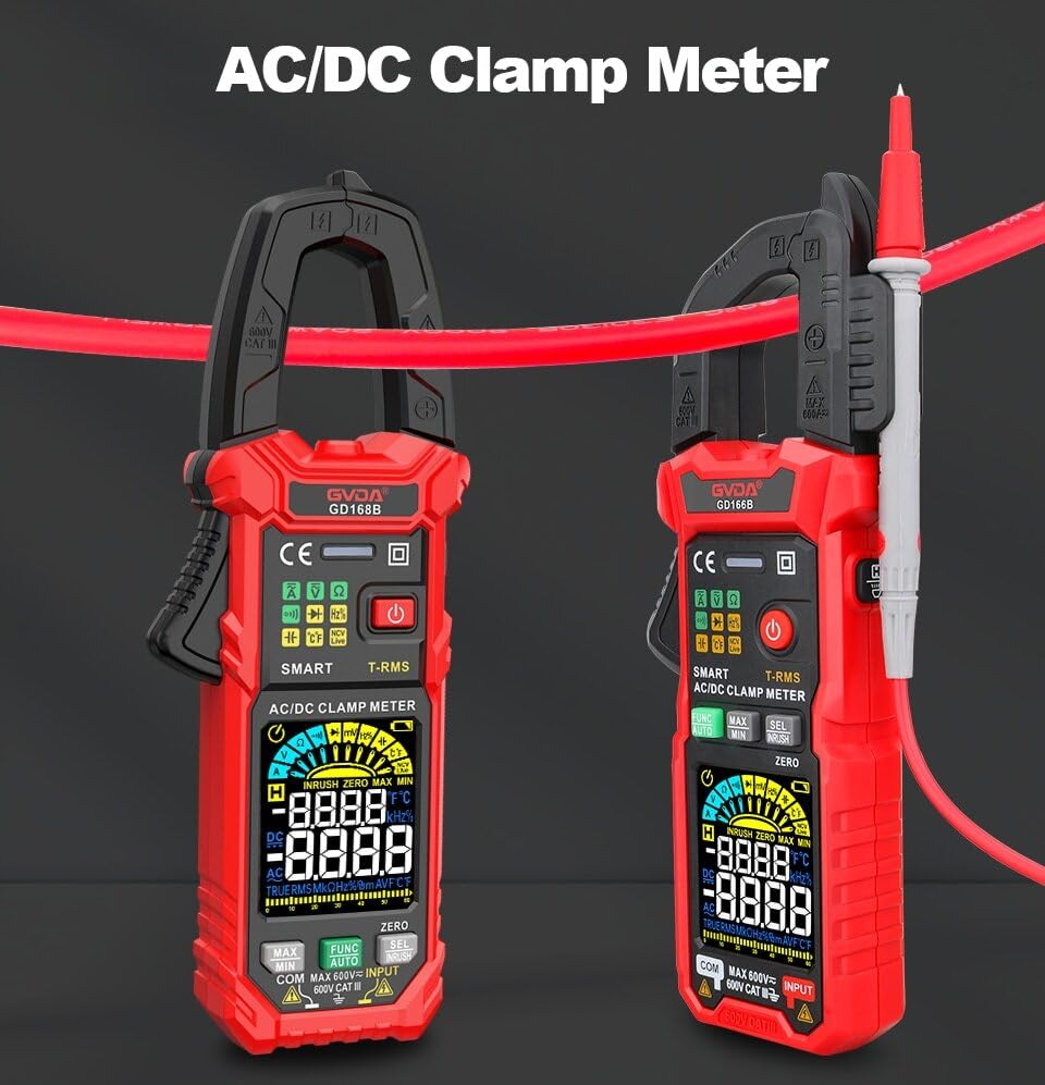
Figure 3.2.3: AC/DC Clamp Meter Comparison. This image displays two GVDA clamp meters, GD168B and GD166B, side-by-side, showcasing their similar design and functionality as AC/DC clamp meters.

Figure 3.2.4: Package Contents. This image shows the complete package contents, including the GD166B clamp meter, test leads, a thermocouple probe, a carrying case, and the user manual.
4. Setup
4.1 Battery Installation
The GD166B requires 3 x 1.5V AAA batteries (not included) for operation.
- Locate the battery compartment on the back of the meter.
- Use a screwdriver to open the battery compartment cover.
- Insert three AAA batteries, ensuring correct polarity (+ and -).
- Replace the battery compartment cover and secure it with the screw.
4.2 Connecting Test Leads
For measurements requiring test leads (e.g., voltage, resistance, continuity, diode, capacitance, temperature), connect them as follows:
- Insert the black test lead into the "COM" (common) input jack.
- Insert the red test lead into the "INPUT" (positive) input jack.

Figure 4.2.1: Test Lead Connection. This image illustrates the correct way to connect the test leads to the meter's input jacks for various measurements.
5. Operating Instructions
5.1 Power On/Off
Press the Power button (⑂) to turn the meter on or off.
5.2 Function Selection
The GD166B features a "Smart Measurement (Auto)" mode, which automatically identifies the measurement type (voltage, resistance, continuity) when test leads are connected. For other specific functions, use the FUNC button to cycle through modes or the rotary dial if present (though this model appears button-driven).
5.3 Common Measurements
5.3.1 AC/DC Voltage Measurement
- Connect the red test lead to the "INPUT" jack and the black test lead to the "COM" jack.
- Select the appropriate voltage range (or use Smart Auto mode).
- Connect the test leads in parallel to the circuit or component to be measured.
- Read the voltage value on the display.
5.3.2 AC/DC Current Measurement (Clamp)
For current measurements, use the clamp jaw. Ensure the circuit is de-energized before clamping.
- Select the AC or DC current function.
- Open the clamp jaw and enclose only one conductor of the circuit.
- Close the clamp jaw completely.
- Read the current value on the display.
5.3.3 Resistance Measurement
- Ensure the circuit is de-energized before measuring resistance.
- Connect the test leads to the "INPUT" and "COM" jacks.
- Select the resistance function.
- Connect the test leads across the component to be measured.
- Read the resistance value on the display.
5.3.4 Continuity Test
- Ensure the circuit is de-energized.
- Connect the test leads to the "INPUT" and "COM" jacks.
- Select the continuity function.
- Connect the test leads across the circuit or component. A continuous beep indicates continuity (low resistance).
5.3.5 Non-Contact Voltage (NCV) Detection
The NCV function allows for detection of AC voltage without direct contact.
- Select the NCV function.
- Place the top end of the meter near the conductor or outlet.
- The meter will beep and the NCV indicator will light up if AC voltage is detected.

Figure 5.3.5.1: NCV Measurement in Progress. This image demonstrates the GD166B clamp meter being used to perform a Non-Contact Voltage (NCV) measurement on an electrical outlet, indicating its ability to detect live voltage without physical contact.
5.3.6 AC Inrush Current Measurement
This function measures the initial surge of current when a device is turned on.
- Select the Inrush Current function.
- Open the clamp jaw and enclose only one conductor of the circuit.
- Turn on the device to be measured. The meter will capture the peak inrush current.

Figure 5.3.6.1: Inrush Current Measurement. This image shows the GD166B clamp meter actively measuring inrush current on a set of electrical wires, demonstrating its capability to capture transient current peaks.
5.3.7 Other Functions
- Data Hold: Press the HOLD button to freeze the current reading on the display. Press again to release.
- MAX/MIN: Press the MAX/MIN button to record the maximum and minimum readings.
- Backlight/Flashlight: Press the Light button to turn on/off the display backlight or the integrated flashlight.
- DCA Zero: Used to zero out the DC current reading before measurement to ensure accuracy.
6. Maintenance
6.1 Cleaning
Wipe the case with a damp cloth and mild detergent. Do not use abrasives or solvents. Keep the input terminals free of dirt or moisture.
6.2 Battery Replacement
When the low battery indicator (battery icon) appears on the display, replace the batteries immediately to ensure accurate readings. Refer to Section 4.1 for battery installation instructions.
6.3 Storage
If the meter is not to be used for an extended period, remove the batteries to prevent leakage and damage to the meter. Store the meter in a cool, dry place, away from direct sunlight and extreme temperatures.
7. Troubleshooting
| Problem | Possible Cause | Solution |
|---|---|---|
| Meter does not power on. | Dead or incorrectly installed batteries. | Check battery polarity; replace batteries. |
| "OL" displayed. | Overload or out of range. | Select a higher range (if applicable) or ensure the measured value is within the meter's limits. |
| Inaccurate readings. | Low battery; incorrect function/range; poor test lead connection. | Replace batteries; select correct function/range; ensure secure test lead connection. |
| No continuity beep. | Circuit not continuous; high resistance; meter not in continuity mode. | Check circuit; ensure resistance is low; select continuity mode. |
8. Specifications
| Parameter | Range/Value |
|---|---|
| DC Voltage | 600mV, 6V, 60V, 600V |
| AC Voltage | 600mV, 6V, 60V, 600V |
| AC Current | 60A, 600A |
| DC Current | 60A, 600A |
| Resistance | 600Ω, 6kΩ, 60kΩ, 600kΩ, 6MΩ, 60MΩ |
| AC Inrush Current | 60A, 600A |
| Capacitance | 6nF, 60nF, 600nF, 6µF, 60µF, 600µF, 6mF, 60mF |
| Frequency | 100Hz, 1000Hz, 10kHz, 100kHz, 1000kHz, 10MHz |
| Duty Cycle | 1-99% |
| Temperature | -40℃ ~ 1000℃, -40℉ ~ 1832℉ |
| Max. Voltage between terminals and Earth Ground | 600V |
| Display | 6000 counts |
| Over Range Indication | "OL" |
| Low Battery Indication | Yes |
| Input Polarity Indication | Display "-" |
| Clamp Opening Size | 36 mm |
| Power Requirement | 3x 1.5V AAA batteries |
| Product Size | 199*81*32 mm |
| Weight (Package) | 440g |
9. Warranty and Support
This product is manufactured to high-quality standards. For information regarding warranty coverage, technical support, or service, please refer to the documentation provided with your purchase or contact your retailer.
Please retain your proof of purchase for warranty claims.


