1. Introduction
The GVDA GD168B is a new generation high-performance True RMS intelligent digital clamp meter designed to make your electrical measurement tasks easier, more efficient, and safer. This versatile instrument combines multiple functions, allowing for precise measurement of AC/DC voltage, AC/DC current, frequency, duty cycle, resistance, capacitance, temperature, diode, continuity, Non-Contact Voltage (NCV), and live wire detection, among others.
Its robust design and comprehensive features make it an essential tool for electricians, technicians, and DIY enthusiasts alike.
2. Safety Information
Always adhere to safety precautions when using any electrical testing equipment. Failure to do so may result in injury or damage to the meter or equipment under test.
- Read this manual thoroughly before operation.
- Do not apply voltage or current that exceeds the maximum rated values specified for the meter.
- Exercise extreme caution when working with live circuits.
- Ensure the test leads are in good condition, free from cracks or damage.
- Do not operate the meter if it appears damaged or is not functioning properly.
- Always disconnect power to the circuit before making resistance, capacitance, or diode measurements.
- Replace batteries promptly when the low battery indicator appears to ensure accurate readings.
3. Product Overview
The GD168B clamp meter features a compact and ergonomic design for comfortable handling and ease of use. Below are the key components and what is included in the package.

Figure 3.1: Front view of the GD168B Clamp Meter with included test leads, showcasing its display and control buttons.
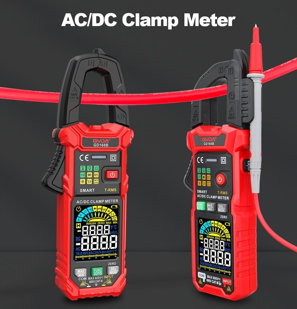
Figure 3.2: Two GD168B Clamp Meters, demonstrating the clamp opening mechanism for AC/DC current measurement.
Package Contents:

Figure 3.3: All items included in the GD168B Clamp Meter package.
- 1 x GD168B Digital Clamp Meter
- 1 x Set of Test Leads
- 1 x Cleaning Cloth
- 1 x Thermocouple Probe
- 1 x User Manual
4. Setup
4.1 Battery Installation
The GD168B clamp meter requires 3 x 1.5V AAA batteries (not included) for operation. To install or replace batteries:
- Locate the battery compartment cover on the back of the meter.
- Use a screwdriver to open the battery compartment.
- Insert the 3 AAA batteries, ensuring correct polarity (+ and -).
- Replace the battery compartment cover and secure it with the screw.
4.2 Connecting Test Leads
For voltage, resistance, capacitance, diode, and continuity measurements, connect the test leads to the appropriate input jacks.

Figure 4.1: Correct connection of test leads for various measurements.
- Insert the red test lead into the "VΩHz" or "INPUT" jack.
- Insert the black test lead into the "COM" (common) jack.
- Ensure a secure connection before taking measurements.
5. Operating Instructions
The GD168B features a smart measurement mode (AUTO) that automatically identifies the measurement type, simplifying operation. You can also manually select specific functions.
5.1 Power On/Off
Press the power button (⏻) to turn the meter on or off. The meter may have an auto-power-off feature to conserve battery life.
5.2 AC/DC Voltage Measurement
- Connect the test leads as described in Section 4.2.
- Select the voltage measurement mode (or use AUTO mode).
- Connect the test probes in parallel to the circuit or component to be measured.
- Read the voltage value on the display.
5.3 AC/DC Current Measurement (Clamp)
For current measurement, use the clamp jaw. Do not use test leads for current measurement with the clamp function.
- Select the AC or DC current measurement mode.
- Open the clamp jaw and enclose only one conductor of the circuit. Ensure the jaw is fully closed.
- Read the current value on the display.
5.4 Inrush Current Measurement
The inrush current function measures the initial surge of current when a device is turned on, useful for diagnosing motor startup issues or circuit breaker tripping.

Figure 5.1: Measuring inrush current on an electrical circuit.
- Select the Inrush Current mode.
- Open the clamp jaw and enclose the conductor of the device you wish to test.
- Turn on the device, and the meter will capture and display the peak inrush current.
5.5 Non-Contact Voltage (NCV) Detection
The NCV function allows for quick and safe detection of AC voltage without direct contact with conductors.

Figure 5.2: Using the NCV function to detect live voltage near an outlet.
- Select the NCV mode.
- Place the NCV sensor (usually at the top of the clamp jaw) near the conductor or outlet.
- The meter will indicate the presence of AC voltage through audible beeps and/or visual indicators.
5.6 Other Functions
- Resistance: Connect test leads to the component. Select resistance mode.
- Capacitance: Connect test leads to the capacitor. Select capacitance mode.
- Frequency/Duty Cycle: Connect test leads to the signal source. Select frequency/duty cycle mode.
- Temperature: Connect the thermocouple probe to the meter and place the probe tip on the object to be measured. Select temperature mode.
- Diode Test: Connect test leads to the diode. Select diode mode.
- Continuity Test: Connect test leads across the circuit or component. Select continuity mode. A beep indicates continuity.
- Data Hold: Press the "HOLD" button to freeze the current reading on the display. Press again to release.
- Backlight/Flashlight: Use the dedicated button to turn on/off the display backlight or the built-in flashlight for working in dimly lit areas.
- MAX/MIN Measurement: Capture the maximum and minimum readings over a period.
- DCA Zero: Used to zero out residual readings in DC current measurement mode for improved accuracy.
6. Maintenance
6.1 Cleaning
Wipe the meter's casing with a damp cloth and mild detergent. Do not use abrasives or solvents. Ensure the meter is dry before storage or use.
6.2 Battery Replacement
Replace batteries when the low battery indicator appears on the display. Refer to Section 4.1 for battery installation instructions.
6.3 Storage
If the meter is not used for an extended period, remove the batteries to prevent leakage. Store the meter in a cool, dry place, away from direct sunlight and extreme temperatures.
7. Troubleshooting
This section addresses common issues you might encounter with your GD168B clamp meter.
| Problem | Possible Cause | Solution |
|---|---|---|
| Meter does not power on. | Dead or incorrectly installed batteries. | Check battery polarity or replace with new AAA batteries. |
| "OL" displayed. | Over-range condition; input value exceeds meter's maximum range. | Ensure the measured value is within the meter's specified range. |
| Inaccurate readings. | Low battery, dirty test leads, or incorrect measurement mode. | Replace batteries, clean test leads, or select the correct measurement function. |
| No continuity beep. | Open circuit or high resistance. | Verify the circuit is closed and resistance is low enough for continuity detection. |
8. Specifications
| Parameter | Value |
|---|---|
| DC Voltage | 600mV, 6V, 60V, 600V |
| AC Voltage | 600mV, 6V, 60V, 600V |
| AC Current | 60A, 600A |
| DC Current | 60A, 600A |
| Resistance | 600Ω, 6kΩ, 60kΩ, 600kΩ, 6MΩ, 60MΩ |
| AC Inrush Current | 60A, 600A |
| Capacitance | 6nF, 60nF, 600nF, 6µF, 60µF, 600µF, 6mF, 60mF |
| Frequency | 100Hz, 1000Hz, 10kHz, 100kHz, 1000kHz, 10MHz |
| Duty Cycle | 1-99% |
| Temperature | -40°C to 1000°C (-40°F to 1832°F) |
| Temperature Unit | °C/°F selectable |
| Max. Voltage between terminals and ground | 600V |
| Display | 6000 counts |
| Over-range Indication | "OL" |
| Low Battery Indication | Yes |
| Input Polarity Indication | "-" display |
| AC/DC mV Measurement | Yes |
| Continuity Test | Yes |
| Max/Min Measurement | Yes |
| Smart Measurement (Auto) | Yes |
| True RMS | Yes |
| Diode Measurement | Yes |
| DCA Zero | Yes |
| Live Wire Detection | Yes |
| Non-Contact AC Voltage Detection (NCV) | Yes |
| Backlight | Yes |
| Flashlight | Yes |
| Data Hold | Yes |
| Clamp Opening Size | 36 mm |
| Power Requirement | 3 x 1.5V AAA Batteries (not included) |
| Package Weight | 440g |
| Product Size | 199x81x32 mm |
9. Warranty and Support
This product comes with a standard manufacturer's warranty. Please refer to the warranty card included in your package for specific terms and conditions. For technical support, troubleshooting assistance, or warranty claims, please contact your retailer or the manufacturer directly.
For further assistance, please visit the official GVDA website or contact their customer service.


