
DEWIN IIQIARXAR
Contents
DeWin 500W MPPT Grid Tie Micro Solar Inverter
User Manual
1. Introduction
This manual provides essential information for the safe and efficient operation of your DeWin 500W MPPT Grid Tie Micro Solar Inverter. Please read this manual thoroughly before installation and operation to ensure proper use and to prevent damage to the unit or connected systems.

Figure 1: DeWin 500W MPPT Grid Tie Micro Solar Inverter
The DeWin 500W MPPT Grid Tie Micro Solar Inverter is a compact and efficient device designed to convert DC power from solar panels or 12V batteries into AC power that can be fed directly into the electrical grid. It features advanced Maximum Power Point Tracking (MPPT) technology to maximize energy harvest and includes robust protection mechanisms for safe and reliable performance.
2. Key Features
- Innovative MPPT Design: Built-in high-precision MPPT algorithm and high-speed power supply capable of capturing sunlight with high accuracy, achieving output power up to 99% efficiency.
- Dual Working Modes: Features a switch for solar panel and battery working modes, allowing independent and reliable operation.
- Adjustable Output Power: Output range can be adjusted from 30W to 250W via a button switch.
- Versatile DC Power Source Compatibility: Compatible with various photovoltaic modules (within starting voltage range) and battery types, including lead-acid, solid, and lithium batteries.
- Low Voltage Protection: Prevents battery capacity fatigue and extends battery life.
- Comprehensive Protection: Includes DC over-voltage/over-current protection, AC over-voltage/over-current/over-frequency protection, and overheat protection for enhanced safety.
3. Product Specifications

Figure 2: Inverter Dimensions and Key Specifications
| Parameter | Value |
|---|---|
| Material | Aluminum Alloy + Copper |
| PV Open Circuit Voltage (12V Model) | 16-28VDC |
| Maximum Input Power PV | 560W |
| MPPT Tracking Voltage (12V Model) | 12-22VDC |
| MPPT Efficiency | >99% |
| Maximum Continuous Current (12V Model) | 35A |
| Applicable Battery Voltage | 12V |
| Low Voltage Protection Value | 11V |
| Maximum Adjustable Output Power (12V Model) | 250W |
| Minimum Adjustable Output Power | 30W |
| Maximum Output Power in PV Mode | 500W |
| Maximum Output Power in Battery Mode (12V Model) | 250W |
| Output Voltage | 220V (185-250VAC) |
| Output Frequency | 50Hz (48-52Hz) |
| Conversion Efficiency | >98% |
| Working Temperature | -25℃ to 80℃ |
| Protection Class | IP22 |
| Cooling Method | Fan |
| Applicable Solar Panels | Monocrystalline, Polycrystalline, Thin-film |
| Package Dimensions | 30.2 x 22.3 x 13.6 cm |
| Weight | 1.7 kg |
4. Setup and Installation
4.1 Safety Precautions
- This inverter is designed for grid-tied operation only. It cannot be used off-grid or as a standalone power source for electrical devices.
- Ensure all connections are secure and correct before powering on the inverter. Incorrect wiring can cause damage to the unit or pose a safety hazard.
- Do not connect high-voltage power boards to low-voltage inverters. Ensure the input voltage matches the inverter's specifications.
- Installation should be performed by qualified personnel in accordance with local electrical codes and regulations.
- Ensure adequate ventilation around the inverter to prevent overheating.
4.2 Connection Diagrams
The inverter supports various connection configurations for solar panels. Always ensure the total voltage and power of your solar array or battery system are within the inverter's specified limits.
4.2.1 Series Connection for Solar Panels

Figure 3: Series Connection of Two 250W Energy Boards
This diagram illustrates the series connection of two photovoltaic energy panels. The no-load voltage after series connection is the sum of the no-load voltages of the two panels, and the working current is the working current of a single panel. For example, with two 250W energy boards, the total power conversion is 500W. The no-load open-circuit voltage of the power boards connected in series is relatively high. Pay attention to whether the input voltage of the inverter matches with it. Remember not to connect high-voltage power boards to low-voltage inverters, otherwise the inverter will be damaged.
4.2.2 Parallel Connection for Solar Panels

Figure 4: Parallel Connection of Two 250W Energy Boards
This diagram illustrates the parallel connection of two photovoltaic energy panels. After parallel connection, the no-load voltage remains unchanged, and the current of the two energy panels is added. For example, with two 250W energy boards, the total power conversion is 500W. The operating voltage (Vmp) remains unchanged, and the operating current is doubled.
4.2.3 Single Solar Panel or Battery Connection
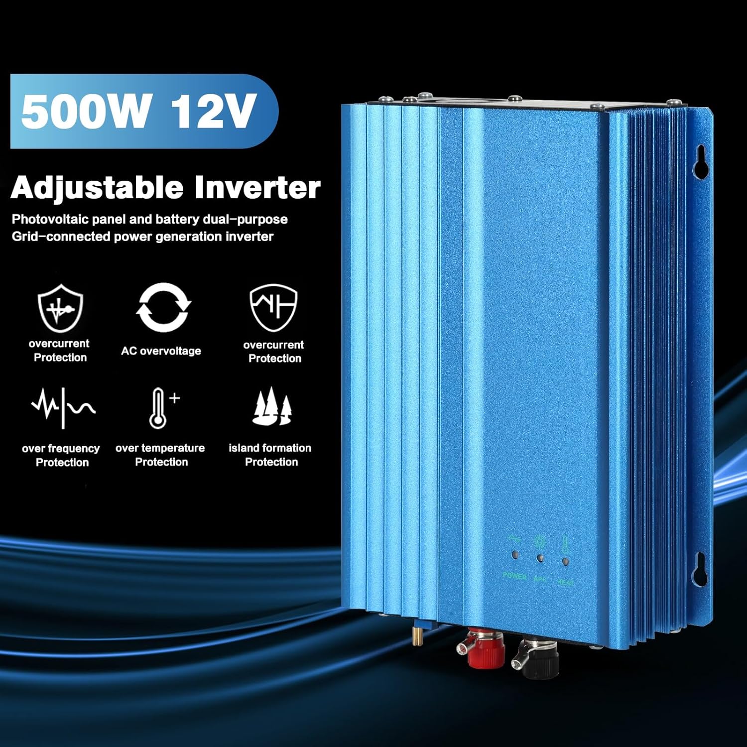
Figure 5: Single Solar Panel or Battery Connection to Inverter
This diagram shows the connection of a single solar panel or a 12V battery to the inverter's DC input. Ensure the recommended solar panel voltage (Vmp: 18-21V, Voc: 20-24V) or 12V battery is used. Connect the AC output of the inverter to a standard home AC outlet.
5. Operation
5.1 Working Modes
The inverter supports two primary working modes: Solar Panel Mode and Battery Mode. These modes can operate independently. A switch allows selection between these modes. The output power can be adjusted from 30W to 250W using the designated button switch.
5.2 LED Indicators
The inverter features three LED indicators (Power, APC, Heat) that provide visual feedback on its operational status. Refer to the table below for their meanings.

Figure 6: Inverter LED Indicators
| LED | Status | Functions |
|---|---|---|
| Power (Indicator Green) | Light Off | System not switched on, or system not connected to solar panel |
| Flashing | PV Voltage or Grid frequency exceeds permitted range | |
| Light On | System in normal working order | |
| APC (Indicator Blue) | Light Off | Input Voltage exceeds MPPT tracking permitted range |
| Flashing | System on tracking the maximum efficiency point of sun lighting | |
| Light On | System locked on the maximum efficiency point of sun lighting | |
| HEAT (Indicator Red) | Light Off | System in normal working temperature, <45℃ |
| Flashing | System is slightly high on temperature, >45℃ | |
| Light On | System is starting to overheat, >70℃, switch output to off, when temperature cools down to below 45℃, device back on to work. |
6. Maintenance
Regular maintenance ensures the longevity and optimal performance of your inverter.
- Cleaning: Periodically clean the exterior of the inverter with a soft, dry cloth. Ensure ventilation openings are free from dust and debris. Do not use liquid cleaners or solvents.
- Connections: Annually inspect all electrical connections (DC input, AC output) to ensure they are tight and free from corrosion.
- Ventilation: Ensure the fan and ventilation areas are not blocked. The fan is crucial for cooling the unit during operation.
- Environment: Keep the inverter in a cool, dry, and well-ventilated area, away from direct sunlight, moisture, and flammable materials.
7. Troubleshooting
This section provides solutions to common issues you might encounter with your inverter.
| Problem | Possible Cause | Solution |
|---|---|---|
| Power LED (Green) is Off | Inverter not powered on or no DC input from solar panel/battery. | Check DC input connections and ensure the solar panels are receiving sufficient sunlight or battery is charged. Verify the inverter's power switch is ON. |
| Power LED (Green) is Flashing | PV voltage or grid frequency is outside the permitted range. | Check the input voltage from solar panels/battery. Verify the grid voltage and frequency are stable and within the inverter's operating limits (185-250VAC, 48-52Hz). |
| HEAT LED (Red) is Flashing | Inverter temperature is slightly high (>45℃). | Ensure adequate ventilation around the inverter. Check for any obstructions blocking the cooling fan or air vents. Reduce load if possible. |
| HEAT LED (Red) is On | Inverter is overheating (>70℃) and has shut down output. | Immediately disconnect the inverter from power sources. Allow it to cool down completely. Check for environmental factors (high ambient temperature, poor ventilation). Once cooled below 45℃, it will resume operation. Address the cause of overheating. |
| No AC Output | No DC input, inverter fault, or grid issue. | Check DC input voltage. Verify AC output connection to the grid. Check LED indicators for error states. If all connections are correct and LEDs show no error, contact support. |
| Lower than Expected Output Power | Insufficient solar input, incorrect MPPT tracking, or power adjustment setting. | Ensure solar panels are clean and receiving full sunlight. Check APC LED status. Verify the adjustable output power setting (30W-250W) is set correctly. For battery mode, ensure battery voltage is sufficient (above 11V). |
8. Warranty and Support
DEWIN products are manufactured to high-quality standards. For warranty information, please refer to the warranty card included with your product or contact your point of purchase. For technical support, troubleshooting assistance, or spare parts, please contact DEWIN customer service through the official channels provided at the time of purchase. Please have your product model number (IIQIARXAR) and purchase details ready when contacting support.
Ask a question about this manual
Ask about setup, troubleshooting, compatibility, parts, safety, or missing instructions. Manuals+ will review the question and use this page’s manual context to help answer it.