Introduction
This document serves as a comprehensive instruction manual for the iCubeSmart GZT-64D LED Canton Tower Model DIY Electronic Kit. This kit provides an engaging project for enthusiasts to assemble a dynamic LED light tower, offering both a hands-on soldering experience and a visually appealing decorative item. Please read all instructions carefully before beginning assembly.

Figure 1: Fully assembled iCubeSmart GZT-64D LED Canton Tower Model.
Safety Information
Please observe the following safety precautions during assembly and operation of your LED Canton Tower Kit:
- Soldering Safety: Soldering irons become extremely hot. Always use appropriate safety gear, including eye protection, and work in a well-ventilated area. Avoid touching the hot tip.
- Electrical Safety: Ensure the power supply is 5V DC. Do not use power adapters with higher voltage. Disconnect power before making any adjustments or repairs.
- Age Restriction: This kit contains small parts and requires soldering. It is not suitable for children under 14 years of age. Adult supervision is recommended for younger users (over 14) or those new to soldering.
- Component Handling: Handle electronic components with care. LEDs are fragile and can be damaged by excessive heat or bending.
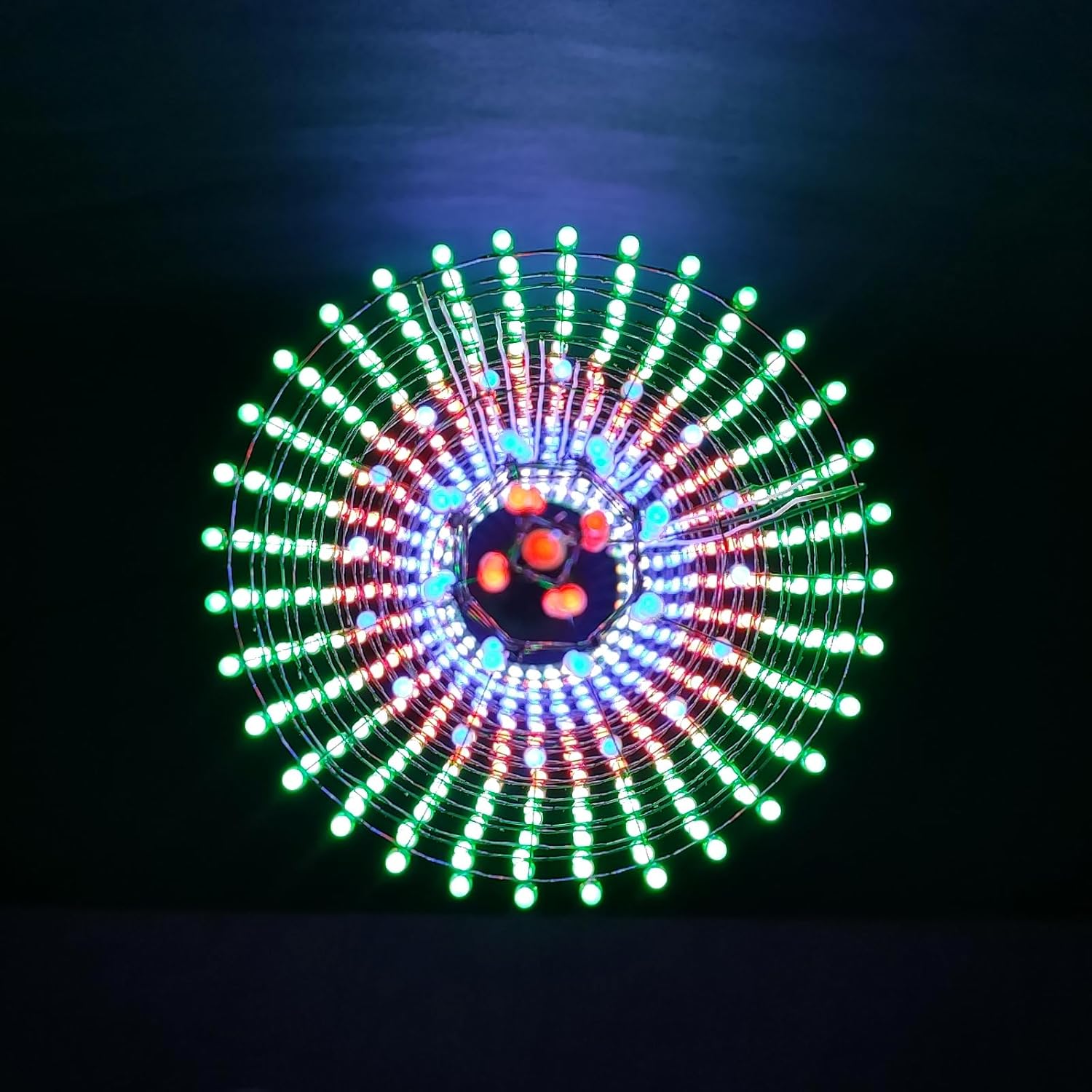
Figure 2: Product packaging with safety warnings and contact information.
Package Contents
Verify that all components listed below are present in your kit before starting assembly:
- Soldered and tested motherboard (15 x 15 cm) x1
- Soldered & Tested Core Plate (Yellow Plate) x1
- Soldered and tested audio board (green plate) x1
- USB download tool + Dupont Line x1
- USB cable x1
- White electronic cable x1
- Plastic mold for auxiliary welding x1
- Fog 3mm LED lamps (standby included):
- 3mm short red LEDs x 600 (uses 512)
- 3mm short green LEDs x 600 (uses 512)
- 3mm short blue LEDs x 600 (uses 552)
- 3mm short pin white LEDs x 600 (uses 512)
- 50 x 3mm Blue LED Lights (additional)
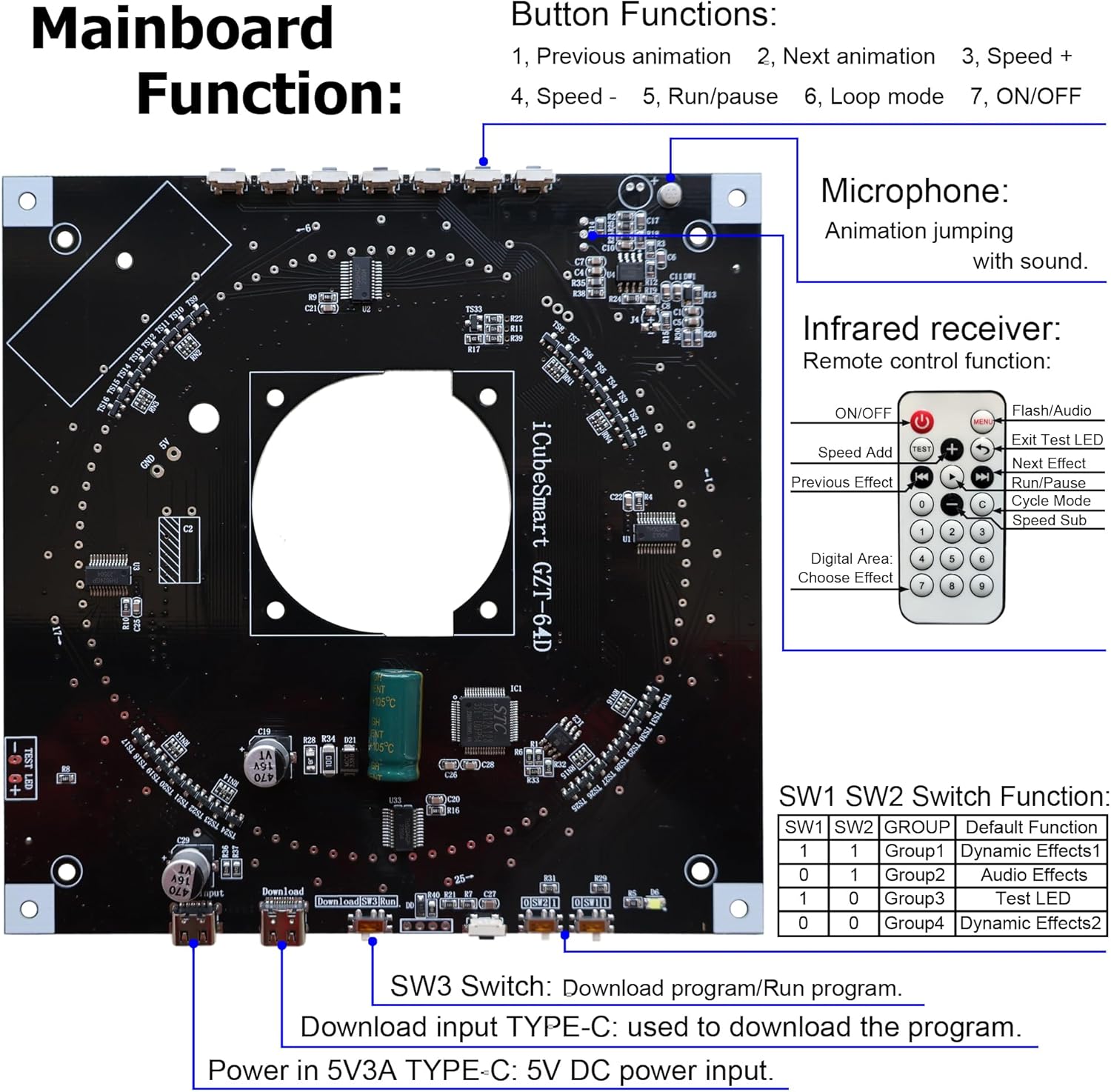
Figure 3: Overview of all components included in the kit.
Assembly Instructions
The iCubeSmart GZT-64D kit requires users to solder the individual LED lamps onto the provided structure. The main motherboard and core plate are pre-soldered and tested to simplify the process. Refer to the detailed welding instructions document for specific LED arrangement methods.
1. LED Preparation and Arrangement
The kit includes four types of 3mm monochrome LEDs. It is crucial to arrange them according to the design for the Canton Tower model. The plastic mold for auxiliary welding will assist in positioning the LEDs correctly.

Figure 4: LED types and quantities required for assembly.
- Green LEDs: 528 pieces used (600 supplied)
- Red LEDs: 512 pieces used (600 supplied)
- Blue LEDs: 560 pieces used (600 supplied, plus 50 additional blue LEDs)
- White LEDs: 512 pieces used (600 supplied)
Ensure correct polarity when inserting LEDs. The longer lead is typically the anode (+), and the shorter lead is the cathode (-). Refer to the specific welding instructions for layer-by-layer LED placement.
2. Soldering the LEDs
Users must possess basic soldering skills for this project. The main board is pre-soldered, but the 2112 LEDs need to be individually soldered onto the structure. Use the provided plastic mold to maintain the correct shape and spacing of the LED layers.

Figure 5: Example of the LED soldering process.
- Heat the soldering iron to an appropriate temperature (typically 300-350°C).
- Place the LED into its designated hole on the structure, ensuring correct polarity.
- Apply the soldering iron tip to both the LED lead and the pad simultaneously for a brief moment.
- Feed a small amount of solder to the joint, allowing it to flow smoothly around the lead and pad.
- Remove the solder, then remove the iron. Allow the joint to cool without disturbance.
- Repeat for all 2112 LEDs.
3. Mainboard and Core Plate Integration
Once all LEDs are soldered and the tower structure is complete, connect it to the pre-soldered motherboard and core plate. Ensure all connections are secure.

Figure 6: Mainboard layout and function diagram.
The mainboard features:
- Buttons: 3 buttons for controlling dynamic effects.
- Microphone Module: For sound-activated dynamic effects.
- Infrared Receiver: For remote control functionality.
- SW1/SW2 Switches: To select dynamic effect groups (Default, Audio, Test, Dynamic Effects 2).
- SW3 Switch: To switch between program download and run modes.
- TYPE-C Port: For USB power (5V DC) and program download.
Operation
After successful assembly, connect the tower to a 5V DC power source using the provided USB cable and TYPE-C port. The tower will power on and display its default dynamic effect.
1. Controlling Dynamic Effects
The tower features multiple dynamic lighting effects that can be controlled via the onboard buttons or the included infrared remote control.
- Onboard Buttons:
- Button 1: Previous animation
- Button 2: Next animation
- Button 3: Speed +
- Button 4: Speed -
- Button 5: Run/Pause
- Button 6: Loop mode
- Button 7: ON/OFF
- Remote Control: Use the infrared remote control for convenient access to all functions, including switching effects, adjusting speed, and power on/off. The remote also allows direct selection of effects by number.
2. Sound-Activated Mode
The integrated microphone module allows the LED tower to react to sound. To activate this mode, set the SW1/SW2 switches to the "Audio Effects" group (refer to Figure 6 for switch settings). In this mode, the dynamic effects will jump and change in response to ambient music or sounds.

Figure 7: Illuminated LED Canton Tower displaying a dynamic light pattern.

Figure 8: Close-up of illuminated LEDs on the tower.
Maintenance
- Cleaning: Gently wipe the tower with a soft, dry cloth to remove dust. Do not use liquid cleaners or abrasive materials.
- Handling: Avoid dropping or subjecting the tower to strong impacts, as this can damage the LEDs or internal components.
- Storage: When not in use, store the tower in a dry, dust-free environment.
Troubleshooting
If you encounter issues with your iCubeSmart GZT-64D LED Canton Tower, refer to the following common problems and solutions:
| Problem | Possible Cause | Solution |
|---|---|---|
| Tower does not light up. | No power, loose connection, faulty power adapter. | Ensure USB cable is securely connected and power adapter is functional. Try a different 5V USB power source. |
| Some LEDs are not lighting. | Poor solder joint, incorrect LED polarity, faulty LED. | Inspect solder joints for cold joints or bridges. Check LED polarity. Replace faulty LEDs if necessary (spare LEDs are provided). |
| Remote control not working. | Battery depleted, line of sight blocked, IR receiver issue. | Replace remote battery. Ensure direct line of sight to the IR receiver on the mainboard. |
| Sound-activated mode not responding. | SW1/SW2 switches incorrect, microphone blocked, insufficient sound. | Verify SW1/SW2 are set to "Audio Effects". Ensure microphone is not covered and sound source is close enough. |
Specifications
| Feature | Detail |
|---|---|
| Model Number | GZT64 |
| Product Dimensions | 5.91 x 5.91 x 39.37 inches (15 x 15 x 100 cm) |
| Item Weight | 1.28 pounds |
| LED Type | 3mm Fog LEDs (Red, Green, Blue, White) |
| Total LEDs | 2112 (512 Red, 512 Green, 552 Blue, 512 White) |
| Microcontroller | GD32F103/STC8H1K28 SCM |
| Power Input | 5V DC via TYPE-C USB |
Warranty and Support
iCubeSmart provides lifetime technical services for all its DIY products. If you require assistance with assembly, operation, or troubleshooting, please contact our technical support team.
Technical Support Email: iCubeSmart@gmail.com
For European Union (EU) and United Kingdom (UK) customers, you may also contact our authorized representatives:
- EU Representative: eVatmaster Consulting GmbH, Bettinastr.30, 60325 Frankfurt am Main, Germany. Email: contact@evatmaster.com
- UK Representative: EVATOST CONSULTING LTD, Suite 11, First Floor, Moy Road Business Centre, Taffs Well, Cardiff, Wales, CF15 7QR. Email: contact@evatmaster.com


