1. Introduction
This manual provides comprehensive instructions for the installation, operation, and maintenance of your YUHANUS Door Access Control System. Please read this manual thoroughly before installation and use to ensure proper functionality and safety.
The YUHANUS Door Access Control System is designed to provide secure and convenient access management for various premises. It features multiple access options including password input, RFID card swiping, and remote control. The system incorporates a robust 600lb electromagnetic lock for enhanced security and includes a doorbell chime for visitor management.
2. Package Contents
Please verify that all components listed below are included in your package:
- Access Control Keypad (CU-K03)
- 600lb Electric Magnetic Lock
- Power Supply Unit (DC12V/4A)
- Exit Button (Push to Exit Switch)
- Doorbell Chime Unit (CU-B01)
- Remote Control Receiver Module
- Two Remote Control Transmitters
- RFID Key Fobs (Blue, 5 included)
- Mounting Hardware (Screws, anchors, L-bracket/Z-bracket if applicable)
- User Manual (This document)

Figure 2.1: Overview of all included components for the access control system.
3. Specifications
| Feature | Specification |
|---|---|
| Brand | YUHANUS |
| Model Number | K03-P9-280-RT |
| Magnetic Lock Holding Force | 600 lbs |
| Power Source | Corded Electric |
| Input Voltage (Power Supply) | AC 110V-240V (1A) 50Hz |
| Output Voltage (Power Supply) | DC 12V (4A) |
| Control Method | Keypad, RFID Card, Remote Control |
| Remote Control Frequency | 433 MHz (approx.) |
| Item Dimensions (L x W x H) | 11.81 x 7.09 x 3.15 inches |
| Material | Stainless Steel (Magnetic Lock) |
| Installation Type | Screw-In |
4. Safety Precautions
- Always disconnect power before performing any installation, wiring, or maintenance.
- Installation should be performed by qualified personnel if you are not familiar with electrical wiring.
- Ensure all wiring connections are secure and properly insulated to prevent short circuits.
- Do not open the power supply unit cover as it contains hazardous voltage.
- Keep the system components away from water and excessive humidity.
- Use only the provided power supply unit or a compatible replacement with the correct voltage and current ratings.
5. Installation and Setup
5.1. Component Identification
Familiarize yourself with the main components:

Figure 5.1.1: Access Control Keypad (CU-K03). This unit allows entry via passcode or RFID card.

Figure 5.1.2: 600lb Electric Magnetic Lock. This is the primary locking mechanism.

Figure 5.1.3: Power Supply Unit. Provides DC 12V power to the system components.
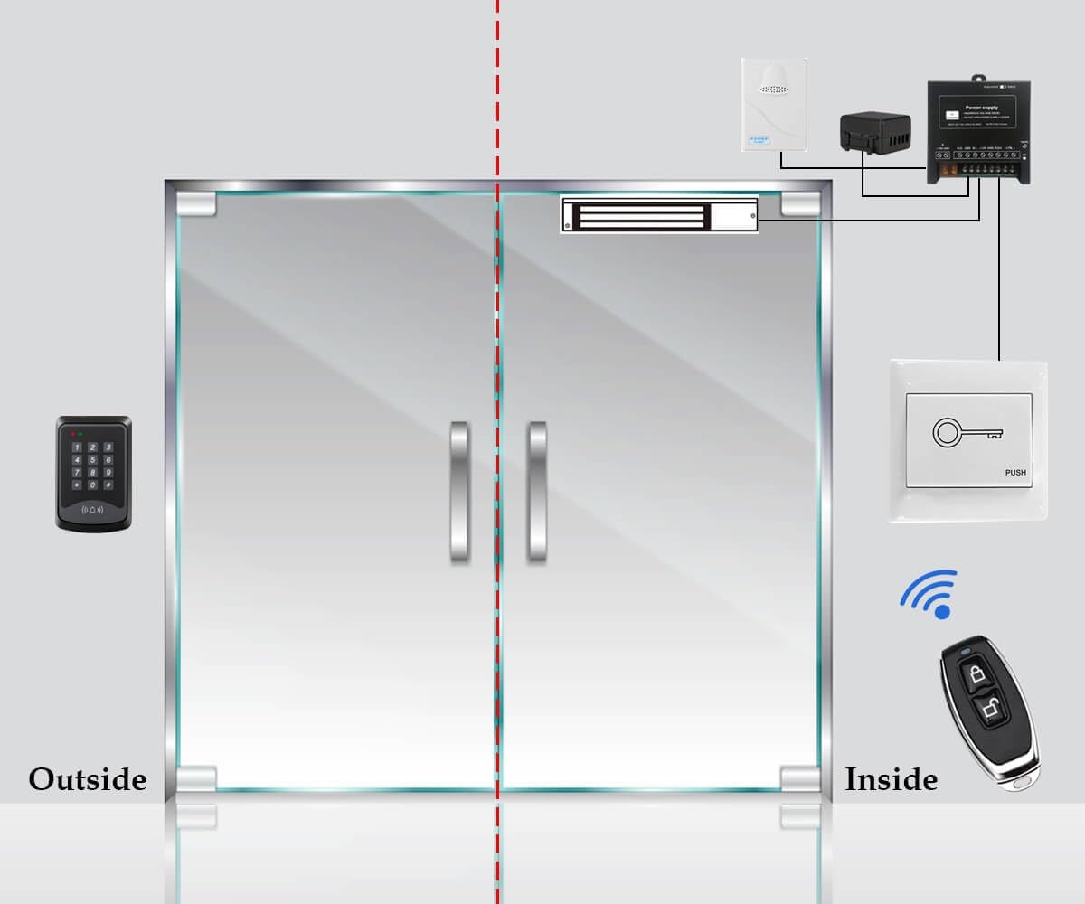
Figure 5.1.4: Exit Button. Allows for easy exit from the secured area.

Figure 5.1.5: Doorbell Chime Unit. Alerts occupants to visitors at the door.

Figure 5.1.6: Remote Control Receiver Module and Transmitters. Enables remote unlocking of the door.
5.2. Wiring Diagram
Follow the wiring diagram carefully for proper connection of all components. Ensure all connections are secure and insulated.

Figure 5.2.1: Comprehensive wiring diagram for the YUHANUS Access Control System, showing connections between the keypad, magnetic lock, power supply, exit button, doorbell, and remote control module.
Key Wiring Points:
- Connect the AC 110V-240V input to the Power Supply Unit.
- The Power Supply Unit provides +12V and GND to the Access Control Keypad and the Magnetic Lock.
- The Magnetic Lock connects to the Power Supply Unit's NO (Normally Open) and GND terminals.
- The Exit Switch Button connects to the PUSH and GND terminals on the Power Supply Unit.
- The Doorbell Chime connects to the BELL terminals on the Access Control Keypad.
- The Remote Control Receiver Module connects to the Power Supply Unit's +12V, GND, NC, and COM terminals.
5.3. Magnetic Lock Installation
The 600lb magnetic lock is designed for surface mounting. Ensure the mounting surface is strong enough to support the lock's holding force.
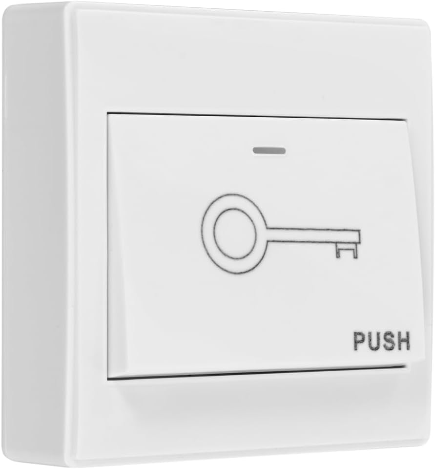
Figure 5.3.1: Dimensions of the 600lb magnetic lock and armature plate.
- Mounting the Magnetic Lock Body: Secure the main magnetic lock body to the door frame using appropriate screws. Ensure it is level and aligned with where the armature plate will be mounted on the door.
- Mounting the Armature Plate: Attach the armature plate to the door. It should align perfectly with the magnetic lock body when the door is closed. Use the provided screws and ensure the plate can pivot slightly to ensure full contact with the electromagnet.
- Adjusting for Alignment: Ensure the magnetic lock and armature plate make full contact when the door is closed. Minor adjustments may be needed for optimal performance.

Figure 5.3.2: Diagram illustrating the installation of the magnetic lock on a door frame and the armature plate on the door.
5.4. System Operation Overview
The system allows access through multiple methods:

Figure 5.4.1: Accessing the door by entering a valid passcode on the keypad.
Figure 5.4.2: Accessing the door by swiping a registered RFID key fob or card.

Figure 5.4.3: Accessing the door remotely using the provided remote control transmitters.
6. Operating Instructions
6.1. Initial Programming (Master Code Setup)
Before first use, you must set up a master code. This code is used to enter programming mode.
- Power on the system.
- Enter the default master code (refer to the keypad's specific manual, typically 123456 or 999999).
- Press # to confirm. The keypad will indicate entry into programming mode (e.g., LED changes color, beeps).
- To change the master code: Press 0, then enter your new 4-6 digit master code, then press #. Re-enter the new master code and press # to confirm.
6.2. Adding User Passcodes
- Enter programming mode using the master code.
- Press 1 (or the designated key for adding users).
- Enter a 4-6 digit user passcode, then press #.
- Repeat for additional user passcodes.
- Exit programming mode (usually by pressing * or waiting for timeout).
6.3. Adding RFID Cards/Key Fobs
- Enter programming mode using the master code.
- Press 2 (or the designated key for adding cards).
- Present the RFID card/key fob to the keypad's reader. The keypad will beep to confirm registration.
- Repeat for additional RFID cards/key fobs.
- Exit programming mode.
6.4. Deleting Users (Passcodes/Cards)
Refer to your keypad's specific manual for detailed deletion procedures. Typically:
- Enter programming mode.
- Press the designated key for deleting users (e.g., 3).
- Enter the specific user passcode or present the RFID card to be deleted.
- Alternatively, some keypads allow deleting all users at once (use with caution).
- Exit programming mode.
6.5. Using the Remote Control
The remote control transmitters are pre-programmed to the receiver module. Press the lock/unlock button on the remote to momentarily release the magnetic lock.
Note: The remote control operates on 433MHz. Be aware of potential interference from other devices operating on the same frequency, such as some wireless doorbells, which might inadvertently trigger the lock.
6.6. Using the Exit Button
Simply press the exit button located inside the secured area to momentarily release the magnetic lock and open the door.
6.7. Using the Doorbell Chime
Visitors can press the doorbell button on the access keypad. The indoor chime unit will sound, alerting occupants.
7. Maintenance
- Cleaning: Wipe the keypad and other components with a soft, dry cloth. Do not use abrasive cleaners or solvents.
- Magnetic Lock Alignment: Periodically check the alignment of the magnetic lock and armature plate. Ensure there is no gap when the door is closed, as this can reduce holding force.
- Wiring Inspection: Annually inspect all wiring connections for signs of wear, corrosion, or loose terminals. Tighten any loose connections.
- Power Supply: Ensure the power supply unit is in a well-ventilated area and free from obstructions.
8. Troubleshooting
| Problem | Possible Cause | Solution |
|---|---|---|
| System has no power / Keypad not lighting up. | No power to the power supply unit; Loose wiring connection; Faulty power supply. | Check power outlet and circuit breaker. Verify all power connections are secure. Test power supply output. |
| Magnetic lock does not engage/disengage. | Incorrect wiring; Insufficient power; Misaligned armature plate; Faulty lock. | Review wiring diagram (Section 5.2). Ensure power supply is providing correct voltage. Adjust armature plate for full contact. Contact support if lock is faulty. |
| Keypad does not respond to input. | No power to keypad; Keypad malfunction. | Check keypad power connections. If power is present, keypad may be faulty. |
| RFID card/key fob not recognized. | Card not programmed; Card damaged; Reader malfunction. | Ensure card is properly programmed (Section 6.3). Try another card. Contact support if reader is faulty. |
| Remote control not working. | Remote battery low/dead; Remote not paired; Receiver module faulty; Interference. | Replace remote battery. Ensure remote is paired with receiver. Check receiver wiring. Minimize other 433MHz devices. |
| Doorbell chime not sounding. | Incorrect wiring; Chime unit faulty. | Verify doorbell wiring to keypad. Test chime unit. |
9. Warranty and Support
YUHANUS products are designed for reliability and performance. For warranty information and technical support, please refer to the contact details provided with your purchase or visit the official YUHANUS website.
Please have your model number (K03-P9-280-RT) and purchase date ready when contacting support.


