
1. Product Overview
This document provides detailed instructions for the DIYmalls 1.44 inch TFT LCD Display Screen Module. This module features a 128x128 pixel resolution with 65K RGB colors and utilizes a 4-wire SPI interface with the ST7735S driver. It is designed for use with various microcontrollers, including Arduino UNO, Arduino 2560, and ESP32 boards.
Key Features:
- 1.44 inch TFT LCD display.
- 128x128 pixel resolution.
- 65K RGB color depth.
- 4-Wire SPI communication interface.
- ST7735S driver IC.
- Operates at 3.3V logic.
- No touch functionality.
2. Technical Specifications
| Specification | Value |
|---|---|
| Brand | DIYmalls |
| Screen Size | 1.44 Inches |
| Resolution | 128 x 128 pixels |
| Aspect Ratio | 1:1 |
| Display Type | TFT LCD |
| Color Depth | 65K RGB |
| Interface | 4-Wire SPI |
| Driver IC | ST7735S |
| Operating Voltage | 3.3 Volts |
| Screen Surface | Glossy |
| Contrast Ratio | 1500:1 |
| Model Number | DIYmalls-1.44-001 |
3. Package Contents
Each package contains:
- 4 x 1.44 inch TFT LCD Display Modules
4. Setup and Wiring Instructions
The DIYmalls 1.44 inch TFT LCD Display operates at 3.3V logic. When connecting to a 5V microcontroller (e.g., some Arduino UNO models), it is crucial to use appropriate voltage level shifters or resistors on the data lines to prevent damage to the display module.
4.1. Pinout Diagram and Description

Image: Pinout of the 1.44 inch TFT LCD Display Module.
| No. | Pin | Description |
|---|---|---|
| 1 | VCC | 5V/3.3V power input |
| 2 | GND | Ground |
| 3 | CS | LCD chip select signal, low level enable |
| 4 | RESET | LCD reset signal, low level reset |
| 5 | A0 | LCD register / data selection signal, high level: register, low level: data |
| 6 | SDA | SPI bus write data signal |
| 7 | SCK | SPI bus clock signal |
| 8 | LED | Backlight control, high level lighting, if not controlled, connect 3.3V always bright |
4.2. Wiring with D1 Mini (ESP8266)
The D1 Mini operates at 3.3V logic, making it directly compatible with this display module without external resistors.

Image: D1 Mini Wiring Diagram.
| No. | LCD Pin | D1 Mini Board Pin | Pin Description |
|---|---|---|---|
| 1 | LED | 3.3V | LCD backlight control pin (connect to 3.3V) |
| 2 | SCK | D5 | LCD SPI bus clock pin |
| 3 | SDA | D7 | LCD SPI bus write data pin |
| 4 | A0 | D3 | LCD register / data selection pin |
| 5 | RESET | D2 | LCD reset control pin |
| 6 | CS | D1 | LCD chip selection control pin |
| 7 | GND | G | Power ground |
| 8 | VCC | 5V | Power positive |
4.3. Wiring with Arduino UNO (5V Microcontroller)
When using a 5V microcontroller like the Arduino UNO, four 560 Ohm, 680 Ohm, or 1k Ohm resistors are required for the data lines (SCK, SDA, A0, and CS) to step down the voltage from the Arduino pins to the 3.3V required by the display. Failure to do so may damage the display module.

Image: Arduino UNO Wiring Diagram.
| No. | LCD Pin | Corresponding to UNO board wiring pins |
|---|---|---|
| 1 | LED | A0 |
| 2 | SCK | 13 |
| 3 | SDA | 11 |
| 4 | A0 | A3 |
| 5 | RESET | A4 |
| 6 | CS | A5 |
| 7 | GND | GND |
| 8 | VCC | 5V/3.3V |
4.4. Wiring with Arduino 2560 (5V Microcontroller)
Similar to Arduino UNO, when using an Arduino 2560, four 560 Ohm, 680 Ohm, or 1k Ohm resistors are required for the data lines (SCK, SDA, A0, and CS) to step down the voltage from the Arduino pins to the 3.3V required by the display.

Image: Arduino 2560 Wiring Diagram.
| No. | LCD Pin | Corresponding to 2560 board wiring pins |
|---|---|---|
| 1 | LED | A0 |
| 2 | SCK | 52 |
| 3 | SDA | 51 |
| 4 | A0 | A3 |
| 5 | RESET | A4 |
| 6 | CS | A5 |
| 7 | GND | GND |
| 8 | VCC | 5V/3.3V |
5. Operation Guide
To operate the display, you will need to use a compatible library for your chosen microcontroller. For Arduino, libraries such as Adafruit GFX Library and Adafruit ST7735 Library are commonly used. These libraries provide functions for drawing text, shapes, and images on the display.
5.1. Example Display Modes
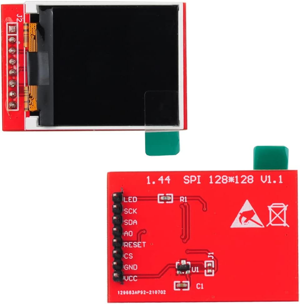
Image: Various display modes and graphics on the 1.44 inch TFT LCD.
5.2. Product Demonstration Video
Video: A demonstration of the DIYmalls 1.44 inch TFT LCD Display (ST7735S) in operation, showcasing its display capabilities and integration with a microcontroller.
6. Troubleshooting
- Display not lighting up: Ensure VCC and GND connections are correct and that the LED pin is connected to 3.3V or controlled by a microcontroller pin set to HIGH.
- No display output or garbled text:
- Verify all SPI data lines (SCK, SDA, A0, CS, RESET) are correctly wired according to the pinout.
- If using a 5V microcontroller, confirm that voltage level shifters or resistors are correctly implemented on the data lines.
- Check that the correct display library (e.g., Adafruit ST7735) is installed and initialized with the correct pin assignments in your code.
- Ensure the SPI clock speed is compatible with the display.
- Incorrect colors: This may indicate an issue with the library initialization or color mode settings in your code. Refer to the library documentation for proper color configuration.
- Display flickering: Check power supply stability and ensure all connections are secure.
7. Maintenance
The DIYmalls 1.44 inch TFT LCD Display Module requires minimal maintenance. Follow these guidelines:
- Handling: Handle the module by its edges to avoid touching the display surface or the delicate FPC (Flexible Printed Circuit) connector.
- Cleaning: If necessary, gently wipe the display surface with a soft, lint-free cloth. Avoid using harsh chemicals or abrasive materials.
- Storage: Store the module in an anti-static bag in a dry environment to prevent damage from static discharge or moisture.
- Power: Always ensure the correct voltage (3.3V logic) is supplied to the display. Over-voltage can cause permanent damage.
8. Support Information
For further assistance, technical documentation, or to explore other DIYmalls products, please visit the official DIYmalls store or contact customer support.
DIYmalls Store: https://www.amazon.com/stores/DIYmalls/page/0EBC2563-CFD4-44A2-9419-85DD5F15E3EF