1. Introduction
This manual provides essential information for the safe and efficient operation of your PowMr 3000W 24V to 110V Pure Sine Wave Solar Inverter. It includes details on product features, installation, operation modes, maintenance, and troubleshooting. Please read this manual thoroughly before installation and use, and retain it for future reference.

Image 1.1: Front view of the PowMr 3000W Solar Inverter.
2. Safety Instructions
Important Safety Precautions:
- Installation must be performed by qualified personnel.
- Ensure all wiring complies with local and national electrical codes.
- Do not disassemble the inverter. There are no user-serviceable parts inside.
- Avoid contact with water or other liquids.
- Install in a well-ventilated area, away from flammable materials.
- Ensure proper grounding before connecting any power sources.
- Verify battery voltage and polarity before connecting to the inverter.
- Always disconnect all power sources (PV, AC, Battery) before performing any maintenance or wiring.

Image 2.1: The inverter features a 12-layer SmartProtect system, including protections against PV input over-voltage, current, reverse connection, battery over-voltage, AC input over-voltage, and inverter overload.
3. Product Overview
3.1 Key Features
- 3000W Pure Sine Wave Inverter: Provides high-quality AC power suitable for sensitive electronics.
- Built-in 80A MPPT Charge Controller: Maximizes solar power harvesting efficiency (up to 99.9%).
- Wide Compatibility: Supports 24V Lead-Acid and Lithium batteries.
- Multiple Charging Modes: Solar, Utility priority, Solar priority, Utility hybrid charging.
- Three Output Modes: PV priority, Utility priority, Inverter mode.
- Comprehensive Protection: Short-circuit, overload, reverse polarity, overvoltage, undervoltage.
- LCD Display & LED Indicators: Real-time monitoring of system data and operational status.
- Max PV Input Power: 4000W, MPPT Voltage range: 120-400Vdc.
3.2 Component Identification

Image 3.1: Front and rear panel components of the inverter.
- LCD Buttons
- Mounting Holes
- LCD Screen
- LED Indicators
- CAN Communication Port
- Dry Contact Port
- RS485 Communication Port
- USB Debugging Port (Internal Use)
- AC Input Terminal
- AC Output Terminal
- Cooling Fans
- PV Input Terminal
- Main On/Off Power Switch
- Battery Input Terminal
- Grounding Lug
4. Setup and Installation
Before Installation: Ensure the mounting surface is strong enough to support the inverter's weight (approximately 19.1 pounds). Choose a location that is dry, well-ventilated, and protected from direct sunlight and extreme temperatures.
4.1 Wiring Diagram

Image 4.1: Wiring diagram for connecting the inverter to solar panels, battery, AC input (utility/generator), and AC output.
Wiring Notes:
- Grounding: Always connect the PE protective conductor (Ground) first.
- Battery Connection: Connect the 24V battery to the Battery Input Terminal. Recommended battery capacity is 200AH. Ensure correct polarity. The battery must be connected for the system to operate.
- PV Input: Connect solar panels in series to the PV Input Terminal. Max PV Input Power: 4000W. MPPT Voltage range: 120-400Vdc. Starting voltage > 150V. Total Open Circuit Voltage (VOC) ≤ 450V. Use 12AWG PV wire.
- AC Input: Connect utility power or a generator to the AC Input Terminal. AC Input Voltage range: 90-140V. Frequency: 50Hz/60Hz. Max AC Bypass Current: 40A. Max AC Charge Current: 40A. Use 10AWG AC wire.
- AC Output: Connect household and office loads to the AC Output Terminal. AC Output Power ≤ 3000W. Rate Voltage: 120Vac ±5%. Rate Current: 27.5A.
5. Operating Instructions
5.1 LCD Display and Indicators
The inverter features an LCD display and LED indicators for real-time monitoring of system data and operational status. The LCD display provides more than 20 programmable parameters, including input/output voltage range, battery charging current, battery type, and charging/discharging priority.

Image 5.1: The LCD display provides real-time monitoring of photovoltaic system operating data.
5.2 Charging Modes
The inverter supports four charging modes:
- Solar Charging: Charges the battery solely from solar power.
- Utility Charge (Solar as backup power): Primarily uses utility power to charge, with solar as a backup.
- Solar Priority: Prioritizes solar power for charging, using utility only when solar is insufficient.
- Solar + Utility Charging: Combines solar and utility power to charge the battery.
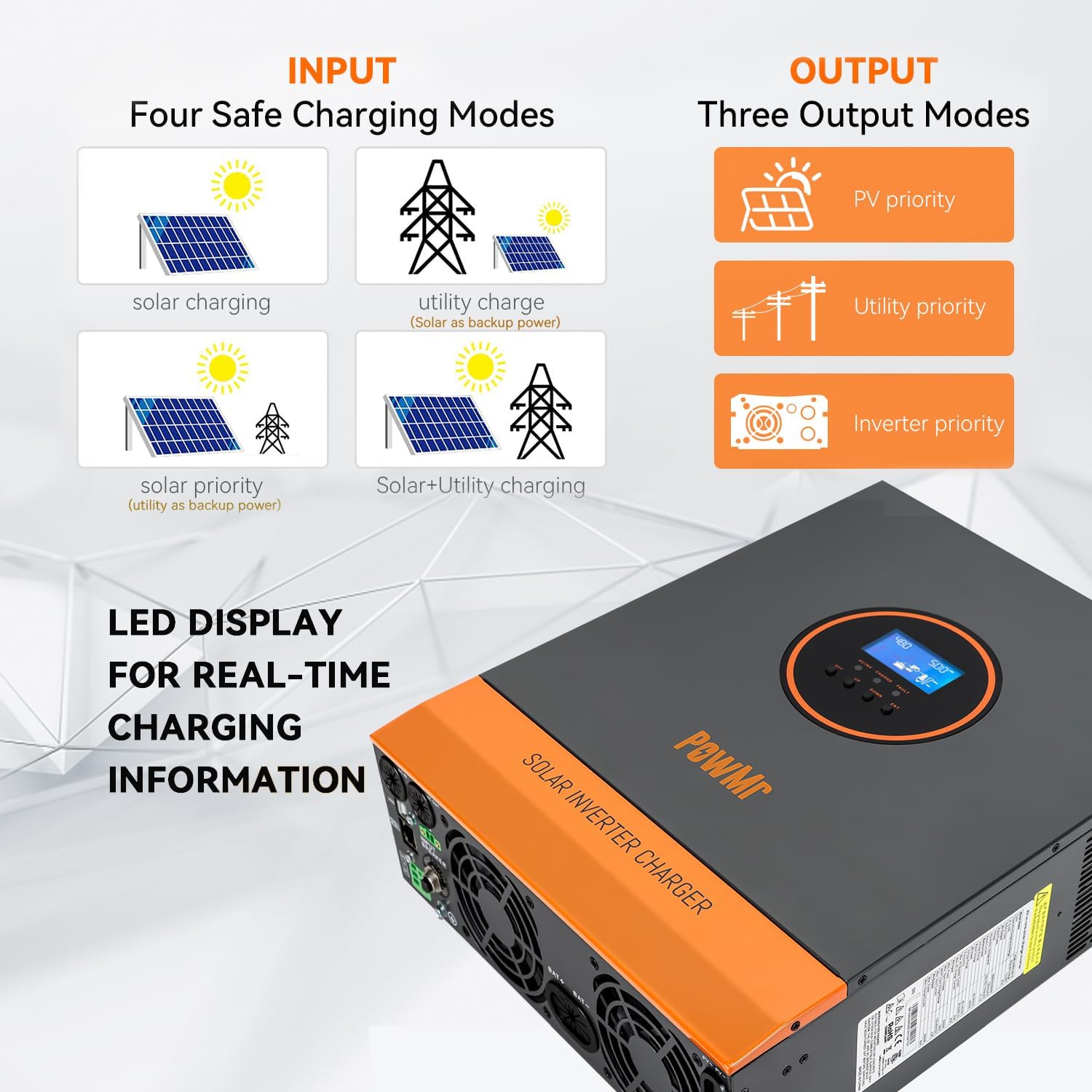
Image 5.2: Visual representation of the four available charging modes.
5.3 Output Modes
The inverter offers three output modes:
- PV Priority: Prioritizes solar power to supply loads.
- Utility Priority: Prioritizes utility power to supply loads.
- Inverter Mode: Uses battery power (converted by inverter) to supply loads.
5.4 Remote Monitoring (Optional)
The inverter supports remote monitoring and control via the SMARTESS App. A Wi-Fi/GPRS data acquisition module is required and needs to be purchased separately. Download the app from the App Store or Google Play.

Image 5.3: Remote monitoring via the SMARTESS App with an optional Wi-Fi module.
Scan the QR code to download the app: Q2721100111238 (Note: Actual download link may vary, refer to product documentation for correct link).
6. Maintenance
Regular maintenance ensures optimal performance and longevity of your inverter. Always disconnect all power sources before performing any maintenance.
- Cleaning: Periodically clean the exterior of the inverter with a dry cloth. Ensure cooling fan vents are free from dust and debris to prevent overheating.
- Connections: Check all electrical connections (battery, PV, AC input/output) regularly for tightness and corrosion.
- Battery Health: Monitor battery voltage and performance. Refer to your battery manufacturer's guidelines for specific maintenance.
- Environment: Ensure the installation environment remains dry, well-ventilated, and within the specified operating temperature range.
7. Troubleshooting
The inverter's LCD display will show corresponding fault codes if a problem occurs. Refer to the product's detailed fault code list (typically found in the full user manual) to identify and resolve issues.
Common Issues and Solutions:
| Problem | Possible Cause | Solution |
|---|---|---|
| Inverter not turning on | No battery connection, low battery voltage, main switch off. | Check battery connections and voltage. Ensure main power switch is ON. |
| No AC output | Overload, short circuit, inverter fault. | Reduce load. Check for short circuits in connected appliances. Refer to LCD fault code. |
| Battery not charging from PV | Insufficient solar input, PV connection issue, MPPT controller fault. | Check solar panel connections and ensure adequate sunlight. Verify PV input voltage is within range (120-400Vdc). |
| Overheating | Blocked cooling vents, excessive ambient temperature, prolonged high load. | Clear vents. Ensure proper ventilation. Reduce load if necessary. |
If the problem persists after attempting these solutions, contact PowMr customer support for assistance.
8. Specifications
| Parameter | Value |
|---|---|
| Model Number | 3000W-24V-110V |
| Rated Power | 3000W |
| Battery Voltage | 24VDC |
| AC Output Voltage | 110V/120VAC ±5% |
| AC Output Frequency | 60 Hz |
| Waveform | Pure Sine Wave |
| MPPT Charge Controller Current | 80A |
| Max PV Input Power | 4000W |
| MPPT PV Voltage Range | 120-400VDC |
| Max PV Open Circuit Voltage | 450VDC |
| AC Input Voltage Range | 90-140V |
| Max Hybrid Charging Current (AC+PV) | 80A |
| Product Dimensions | 16.53 x 12.59 x 4.72 inches |
| Item Weight | 19.1 pounds |
| Compatible Battery Types | Lead-Acid, Lithium |
9. Warranty and Support
For warranty information and technical support, please contact PowMr directly. Refer to the product packaging or the official PowMr website for the most current contact details and warranty terms.
Manufacturer: PowMr
Date First Available: May 16, 2023


