1. Introduction
This manual provides detailed instructions for the installation, operation, and maintenance of the Dixell XR06CX-5N0C1 Digital Thermostat Controller. This device is designed for refrigerating and freezing units, offering precise temperature control, defrost management, and fan operation. Please read this manual thoroughly before installation and use to ensure proper functioning and safety.

Figure 1: The Dixell XR06CX-5N0C1 Digital Thermostat Controller, showing the main unit, included temperature probe sensors, and the wiring diagram printed on the top label. This image provides an overview of the product and its components.
2. Safety Information
- Disconnect all power before performing any electrical connections or maintenance.
- Ensure all wiring complies with local electrical codes and regulations.
- The controller should be installed in a location protected from water, excessive humidity, and direct sunlight.
- Do not use the device for purposes other than those described in this manual.
- Only qualified personnel should perform installation and servicing.
3. Installation and Mounting
3.1 Mounting the Controller
The XR06CX-5N0C1 controller is designed for panel mounting.
- Cut a panel opening of 71 x 29 mm (2.8" x 1.14").
- Insert the controller into the opening.
- Secure the controller using the provided mounting clips.
Figure 2: The Dixell XR06CX-5N0C1 controller shown with the included mounting clips, which are used to secure the unit into a panel cutout.
3.2 Electrical Connections
All electrical connections must be made with the power supply disconnected. Refer to the wiring diagram on the controller's label and Figure 3 for correct connections.
- Power Supply: Connect 230V AC, 50/60Hz to terminals 1 and 2.
- Compressor Output: Connect the compressor load to terminals 3 and 4 (10A relay).
- Defrost Output: Connect the defrost heater load to terminals 5 and 6 (8A relay).
- Fan Output: Connect the fan load to terminals 7 and 8 (5A relay).
- Probe 1 (Thermostat): Connect the NTC temperature probe to terminals 9 and 10. This probe controls the thermostat function.
- Probe 2 (Defrost/Evaporator): Connect the second NTC temperature probe to terminals 11 and 12. This probe is typically used for defrost termination.

Figure 3: Rear view of the Dixell XR06CX-5N0C1 controller, illustrating the terminal block for electrical wiring connections. Each terminal is clearly labeled for power, outputs (compressor, defrost, fan), and temperature probes.

Figure 4: Top view of the Dixell XR06CX-5N0C1 controller, highlighting the detailed wiring diagram printed on the unit's label. This diagram is crucial for correct electrical installation.
4. Operating Instructions
4.1 Front Panel Controls and Display
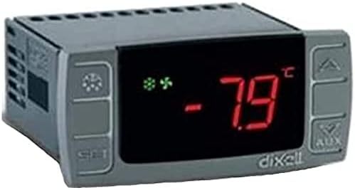
Figure 5: Front view of the Dixell XR06CX-5N0C1 controller, showing the LED display indicating a temperature of -7.9°C and various status icons for compressor, defrost, and fan operation.
- Display: Shows the current temperature measured by Probe 1 (thermostat probe) or other parameters during programming.
- SET Button: Used to view and modify the set point, or to access programming parameters.
- UP (▲) Button: Increases the displayed value or scrolls through parameters.
- DOWN (▼) Button: Decreases the displayed value or scrolls through parameters.
- AUX Button: Activates/deactivates auxiliary functions or initiates a manual defrost.
- LED Indicators: Various LEDs indicate the status of the compressor, defrost, fans, and alarms.
4.2 Setting the Temperature Setpoint
- Press and release the SET button. The current setpoint value will be displayed.
- Use the UP (▲) or DOWN (▼) buttons to adjust the setpoint to the desired temperature.
- Press the SET button again to confirm and save the new setpoint.
4.3 Unlocking the Keyboard
If the keyboard is locked, the "On" message will be displayed when attempting to change parameters. To unlock:
- Press and hold the UP (▲) and DOWN (▼) buttons simultaneously for more than 3 seconds.
- The "On" message will disappear, indicating the keyboard is unlocked.
4.4 Manual Defrost
To initiate a manual defrost cycle:
- Press and hold the AUX button for more than 3 seconds.
- The defrost cycle will begin, indicated by the defrost LED.
5. Maintenance
5.1 Cleaning
Clean the controller's front panel periodically with a soft, damp cloth. Do not use abrasive cleaners, solvents, or harsh chemicals, as these can damage the display or casing.
5.2 Probe Inspection
Regularly inspect the temperature probes and their wiring for any signs of damage or corrosion. Ensure they are securely connected and properly positioned within the refrigerating unit. Damaged probes should be replaced immediately to maintain accurate temperature control.
6. Troubleshooting
This section addresses common issues you might encounter with the Dixell XR06CX-5N0C1 controller.
| Problem | Possible Cause | Solution |
|---|---|---|
| Display shows "P1" or "P2" | Probe 1 (P1) or Probe 2 (P2) error (open circuit or short circuit). | Check the probe connections. If connections are secure, replace the faulty probe. |
| Display shows "HA" or "LA" | High (HA) or Low (LA) temperature alarm. Temperature is outside the set alarm limits. | Check the refrigeration unit's operation. Verify door seals, refrigerant levels, or compressor function. Adjust alarm limits if necessary. |
| Controller does not power on | No power supply or incorrect wiring. | Verify the 230V AC power supply to terminals 1 and 2. Check all wiring connections for looseness or errors. |
| Compressor not starting | Temperature above setpoint, defrost cycle active, or compressor delay. | Check the current temperature. Wait for defrost cycle to complete or for compressor delay to expire. Verify compressor wiring. |
7. Specifications
- Model: Dixell XR06CX-5N0C1
- Power Supply: 230V AC, 50/60Hz
- Inputs: 2 NTC Temperature Probes
- Outputs:
- Compressor: 10A relay (R3A 250V~)
- Defrost: 8A relay (R2A 250V~)
- Fans: 5A relay (R1A 250V~)
- Display Type: LED
- Operating Temperature Range: 0°C to 60°C (32°F to 140°F) (Note: The specification "1.1E+2 Degrees Celsius" from product data likely refers to a different parameter or is an error; the unit's label indicates 0-60°C.)
- Product Dimensions (L x W x H): 71mm x 29mm x 56mm (2.8" x 1.14" x 2.2")
- UPC: 716709827977
- Manufacturer: LSBYLM (Brand: Dixell)
8. Warranty and Support
Information regarding product warranty and customer support is not provided within this manual. Please refer to your purchase documentation or contact the seller/manufacturer directly for details on warranty coverage and technical assistance.