
1. Introduction
This manual provides detailed instructions for assembling and operating your ETAxopowo DIY Electronic Clock Kit. This kit is designed as a soldering project, allowing users to build a functional digital clock with multiple display features. Please read all instructions carefully before beginning assembly.
1.1 Product Overview
The ETAxopowo DIY Electronic Clock Kit features a 4-digit green LED display capable of showing time, week, temperature, and date. It includes various display modes, alarm functions, temperature unit selection (Celsius/Fahrenheit), adjustable brightness, and built-in music.

Image 1.1: Assembled clock and all kit components.
1.2 Kit Contents
Before starting, verify that all components listed below are present in your kit:

Image 1.2: All kit components laid out for inspection.
- Printed Circuit Board (PCB)
- 4-Digit Green LED Display Module
- Microcontroller IC (IAP15W413AS or STC8G1K17)
- Real-Time Clock (RTC) IC (DS1302)
- Resistors (various values)
- Capacitors (various values)
- Crystal Oscillator
- Transistor
- Buzzer
- Push Buttons (UP, DOWN, SET)
- DC Power Jack
- USB Power Cable
- CR1220 Battery Holder and CR1220 Battery
- Photoresistor and Thermistor
- Acrylic Case Components and Screws
2. Safety Information
This kit involves soldering, which requires caution. Please observe the following safety guidelines:
- Always work in a well-ventilated area to avoid inhaling solder fumes.
- Wear safety glasses to protect your eyes from solder splashes or flying component leads.
- Use a soldering iron stand to prevent accidental burns.
- Ensure the soldering iron tip is clean and properly tinned.
- Disconnect power before handling components or making adjustments to the circuit.
- Keep components and tools away from children.
3. Assembly Instructions
Follow these steps carefully to assemble your electronic clock kit. Refer to the provided images for visual guidance. A soldering iron, solder, and wire cutters are required.
3.1 Soldering Components to the PCB

Image 3.1: Soldering steps 1-6.
- Step 1: Install the four 10kΩ resistors. Resistors do not have polarity.
- Step 2: Install the crystal oscillator. This component does not have polarity.
- Step 3: Install the ceramic capacitors. These components do not have polarity.
- Step 4: Install the battery holder. Ensure correct orientation if marked.
- Step 5: Install the IC holder. Align the notch on the holder with the corresponding notch on the PCB silkscreen.
- Step 6: Install the buzzer. Pay attention to the positive (+) terminal, aligning it with the marked position on the circuit board.
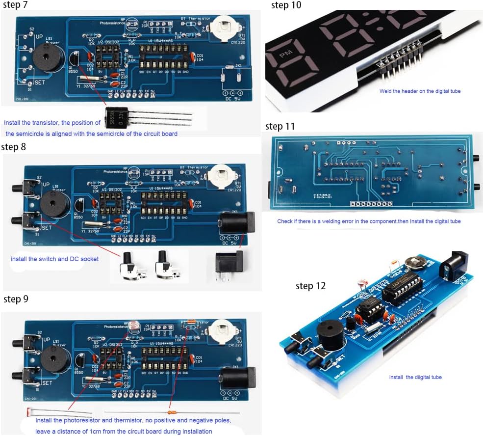
Image 3.2: Soldering steps 7-12.
- Step 7: Install the transistor. Align the semicircular side of the transistor with the semicircular marking on the circuit board.
- Step 8: Install the switches (UP, DOWN, SET) and the DC socket.
- Step 9: Install the photoresistor and thermistor. These components do not have polarity. Leave a distance of approximately 1cm from the circuit board during installation.
- Step 10: Solder the header pins onto the digital tube display module.
- Step 11: Check for any soldering errors on the main PCB. Then, install the digital tube display module by inserting its header pins into the corresponding sockets on the main PCB.
- Step 12: Install the digital tube display module. Ensure it is seated correctly.
3.2 Installing Integrated Circuits (ICs) and Battery
- Step 13: Install the DS1302 (RTC) and IAP15W413AS (Microcontroller) ICs into their respective sockets. Pay close attention to the notch or dot on the ICs, aligning them with the corresponding markings on the IC sockets.
- Step 14: Install the CR1220 battery into its holder. Ensure the positive (+) side of the battery faces upwards, aligning with the positive terminal of the holder.
3.3 Final Adjustments and Case Assembly
- Step 15: Adjust the position of the photoresistor and thermistor so they are exposed and can accurately sense ambient light and temperature.
- Step 16: Assemble the acrylic case around the completed circuit board. Secure it with the provided screws.
4. Operating Instructions
Once assembled, connect the clock to a 5V USB power source using the provided cable. The clock will power on and display the current time or default display mode.
4.1 Buttons Overview
- SET Button: Enters/exits setting modes, confirms selections.
- UP Button: Increases values, navigates menu options.
- DOWN Button: Decreases values, navigates menu options.
4.2 Display Modes
The clock supports multiple display modes, which can typically be cycled through by pressing a specific button (often the UP or DOWN button when not in setting mode). The available modes include:

Image 4.1: Examples of various display modes.
- Time-Temperature
- Time-Date-Week
- Time-Temperature-Date-Week
4.3 Setting Time and Date
To set the time and date:
- Press the SET button to enter the setting mode. The first parameter (e.g., hour) will start blinking.
- Use the UP or DOWN buttons to adjust the value.
- Press SET again to move to the next parameter (e.g., minute, year, month, day).
- Repeat until all parameters are set. Press SET one last time to exit the setting mode.
4.4 Alarm Settings
The clock supports up to three alarms. To set an alarm:
- Enter the alarm setting mode (usually by pressing SET multiple times until 'AL1' or similar appears).
- Use UP/DOWN to set the alarm hour and minute.
- Enable/disable the alarm and set the alarm to work on specific days (e.g., Monday to Friday).
- Repeat for AL2 and AL3 if desired.
4.5 Temperature Display
The temperature can be displayed in Celsius (°C) or Fahrenheit (°F). This setting is typically found within the general settings menu. Use the UP/DOWN buttons to select the desired unit and SET to confirm.
4.6 Brightness Adjustment
The clock features adjustable brightness and an automatic brightness mode via a light sensor. To adjust:
- Access the brightness setting in the menu.
- Use UP/DOWN to select a manual brightness level or enable the automatic brightness feature.
4.7 Other Features
- Time Correction: A function to improve clock accuracy. Refer to the online tutorial for detailed calibration steps.
- Hourly Chime: Can be set to prompt during specific hours (default 7:00-21:00).
- Built-in Music: Includes three melodies (To Alice, Ode to Joy, Spanish Matador) for alarms.
- Power-off Memory: The CR1220 battery maintains time settings during power outages.
5. Maintenance
To ensure the longevity and proper functioning of your ETAxopowo Electronic Clock Kit:
- Keep the clock in a dry environment, away from moisture and extreme temperatures.
- Clean the acrylic case with a soft, dry cloth. Avoid abrasive cleaners.
- If the timekeeping becomes inaccurate after a power outage, replace the CR1220 backup battery.
- Avoid dropping the clock or subjecting it to strong impacts.
6. Troubleshooting
If you encounter issues with your clock, refer to the following common problems and solutions:
| Problem | Possible Cause | Solution |
|---|---|---|
| Display is blank or dim. | No power, loose connection, incorrect brightness setting. | Check USB power connection. Ensure digital tube is properly seated. Adjust brightness settings. |
| Clock does not keep accurate time. | Faulty crystal oscillator, incorrect time correction setting, dead backup battery. | Verify crystal oscillator soldering. Check time correction settings. Replace CR1220 backup battery. |
| Buttons are unresponsive. | Loose button connections, faulty buttons. | Inspect button soldering. Ensure buttons are not stuck. |
| Temperature reading is incorrect. | Faulty thermistor, incorrect unit setting. | Verify thermistor soldering and exposure. Check if temperature unit is set to Celsius or Fahrenheit. |
| Alarm does not sound. | Alarm disabled, incorrect time setting, faulty buzzer. | Ensure alarm is enabled and set correctly. Verify buzzer soldering. |
7. Specifications
Detailed technical specifications for the ETAxopowo DIY Electronic Clock Kit:

Image 7.1: Clock dimensions and main ICs.
- Brand: ETAxopowo
- Model: B0C4PP1LNJ
- Display: 4-Digit Green LED
- Microcontroller IC: IAP15W413AS or STC8G1K17
- Real-Time Clock IC: DS1302
- Crystal Oscillator: 5ppm high-precision
- Power Input: USB 5V
- Backup Battery: CR1220 (for power-off memory)
- Functions: Time (12/24H), Date, Week, Temperature (°C/°F), 3 Alarms, Adjustable Brightness (manual/auto), Hourly Chime, 3 Built-in Music melodies.
- Material: Plastic (case)
- Product Dimensions (L x W x H): Approximately 4.5 x 1.2 x 1.5 inches (11.5 x 3.2 x 4 cm)
- Item Weight: Approximately 3.53 ounces (100 Grams)
- UPC: 714487351288
7.1 Circuit Diagram

Image 7.2: Detailed circuit diagram of the clock kit.
8. Warranty and Support
This DIY kit is intended for educational and hobbyist purposes. Due to the nature of a DIY soldering project, specific warranties may vary. Please refer to the seller's policy for return or replacement information.
For additional support, including detailed soldering videos and advanced settings, please consult the online resources provided by the manufacturer or seller. A QR code or web link is typically included with the physical product for these resources.