
1. Introduction
The BSIDE A5X is a versatile and intelligent automatic digital multimeter designed for precise electrical measurements. Featuring a vibrant EBTN color LCD, it provides clear readings including test values, analog bars, and frequency/temperature. This device is equipped with smart auto-ranging capabilities, making it user-friendly for both beginners and experienced professionals. Its rechargeable lithium battery ensures long-lasting performance, and robust safety features provide protection against overload and burnout.
1.1. What's in the Box
- BSIDE A5X Rechargeable Multimeter
- Test Leads (Red and Black)
- Protective EVA Case
- Thermocouple (Temperature Probe)
- Type-C Charging Cable
- User Manual (English)

Figure 1.1: BSIDE A5X Multimeter with included test leads, charging cable, thermocouple, and protective case.
2. Safety Information
Please read and understand all safety warnings and operating instructions before using this multimeter. Failure to do so may result in injury or damage to the meter or equipment under test.
- Always ensure the test leads are properly connected and the function selected is appropriate for the measurement.
- Do not exceed the maximum input values specified for each range.
- Exercise extreme caution when working with live electrical circuits.
- Do not use the meter if it appears damaged or if the test leads are frayed.
- Replace the fuse only with the specified type and rating.
- Keep hands and fingers behind the probe barriers during measurements.
- Avoid using the meter in wet environments or during electrical storms.
3. Setup
3.1. Charging the Battery
The BSIDE A5X is equipped with a built-in 700mAh rechargeable lithium-ion battery. Before first use, or when the low battery indicator appears, charge the device using the provided Type-C charging cable.
- Connect the Type-C end of the charging cable to the multimeter's charging port.
- Connect the USB-A end of the cable to a standard USB power adapter (not included) or a computer USB port.
- The charging indicator on the multimeter will show the charging status. Once fully charged, the indicator will change or turn off.

Figure 3.1: The BSIDE A5X Multimeter features a built-in rechargeable 700mAh Li-ion battery, eliminating concerns about power depletion.
3.2. Initial Power On
Press and hold the power button (⏻) to turn on the multimeter. The device will typically start in Smart Mode, automatically detecting the measurement type.
4. Operating Instructions
The BSIDE A5X features an intelligent auto-identification system that simplifies measurements. In Smart Mode, it automatically detects and measures AC/DC voltage, AC/DC current, resistance, continuity, and frequency. For other functions, use the dedicated buttons.
4.1. Smart Mode Operation
When powered on, the multimeter defaults to Smart Mode. Simply connect the test leads to the circuit or component, and the meter will automatically identify and display the measurement (Voltage, Current, Resistance, Continuity, or Frequency).
4.2. Measuring AC/DC Voltage
In Smart Mode, the meter automatically measures AC or DC voltage. Connect the red test lead to the 'VΩHz' input jack and the black test lead to the 'COM' input jack. Place the probes across the circuit points to measure voltage.

Figure 4.1: The BSIDE A5X Multimeter automatically measures AC voltage, displaying both the voltage value and frequency.
4.3. Measuring AC/DC Current
For current measurements, the A5X features smart identification. Plug the test leads into the appropriate current input port (600mA for current measurements) and the 'COM' port. The tester will automatically switch to AC/DC ampere test mode.
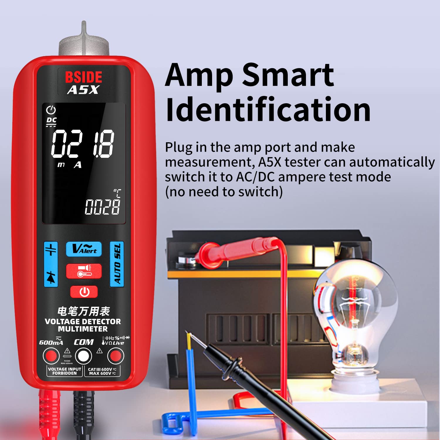
Figure 4.2: The BSIDE A5X Multimeter features Amp Smart Identification; simply plug into the amp port, and the tester automatically switches to AC/DC ampere test mode.
4.4. Measuring Resistance
In Smart Mode, connect the test leads across the resistor. The meter will automatically detect and display the resistance value.
4.5. Measuring Capacitance
To measure capacitance, press the 'FUNC' button until the capacitance symbol (μF) appears on the display. Important: Always discharge the capacitor before measuring to prevent damage to the meter or injury. Connect the test leads across the capacitor terminals.

Figure 4.3: Capacitance Test. Always discharge the capacitor before measuring to ensure safety and accurate readings.
4.6. Measuring Frequency and Duty Cycle
In Smart Mode, frequency is automatically displayed when measuring AC voltage. For dedicated frequency or duty cycle measurements, press the 'FUNC' button to cycle through modes until the Hz or % symbol appears. Connect the test leads to the signal source.
4.7. Measuring Temperature
Connect the provided thermocouple to the multimeter's input jacks (ensure correct polarity). Press the 'FUNC' button until the temperature symbol (°C or °F) appears. Place the thermocouple probe at the point where temperature needs to be measured. The A5X can display both thermometer temperature and ambient environment temperature.

Figure 4.4: Dual-Way Temperature Test. The multimeter can measure both thermometer temperature (0°C~1000°C) and environment temperature (0°C~50°C).
4.8. Diode Test
Press the 'FUNC' button to select the diode test mode. Connect the red test lead to the anode and the black test lead to the cathode of the diode. The display will show the forward voltage drop. For a good silicon diode, this is typically around 0.5V to 0.8V. An open circuit (OL) indicates a faulty diode or incorrect polarity.
4.9. Continuity Test
In Smart Mode, continuity is automatically detected. Alternatively, press the 'FUNC' button to select continuity mode. Connect the test leads across the circuit or component. If the resistance is below approximately 30Ω, the meter will emit an audible beep, indicating continuity.
4.10. Non-Contact Voltage (NCV) Detection
The NCV function allows for detection of AC voltage without direct contact. Press the 'V-Alert' button to activate NCV mode. Move the top tip of the multimeter near the conductor. The meter will indicate the presence of AC voltage through visual and audible alerts. The A5X offers high and low sensitivity settings for NCV detection.
4.11. VFC (Variable Frequency Control) Test
The VFC function is designed to measure the output voltage of variable frequency drives (VFDs) or inverters. Press the 'FUNC' button to select VFC mode. Connect the test leads to the output of the VFD. This mode provides accurate readings for non-sinusoidal waveforms.

Figure 4.5: The VFD function allows the BSIDE A5X Multimeter to accurately measure the output voltage of inverters.
4.12. Automotive Circuit Test
The BSIDE A5X can be used for various automotive electrical tests, such as checking battery voltage, alternator output, and continuity in wiring. Ensure the vehicle's electrical system is off before connecting test leads for continuity or resistance checks. For voltage checks, connect leads to the appropriate points (e.g., battery terminals).

Figure 4.6: The BSIDE A5X Multimeter is suitable for various automotive circuit tests, including battery voltage checks.
5. Maintenance
5.1. Cleaning
Wipe the meter's casing with a damp cloth and mild detergent. Do not use abrasives or solvents. Ensure the meter is off and disconnected from any circuits before cleaning.
5.2. Battery Care
To prolong battery life, avoid fully discharging the battery frequently. Recharge the battery when the low battery indicator appears. If storing the meter for an extended period, charge it periodically to maintain battery health.
5.3. Fuse Replacement
The BSIDE A5X is equipped with an easy-to-replace fuse for overload protection. If the current measurement function stops working, the fuse may need replacement. Refer to the specifications for the correct fuse type and rating. Disconnect all test leads and power off the meter before attempting fuse replacement.
6. Troubleshooting
- No Display/Meter Not Turning On: Check battery charge level. Ensure the power button is pressed and held sufficiently.
- Incorrect Readings: Verify test lead connections. Ensure the correct measurement function is selected (if not in Smart Mode). Check for damaged test leads.
- No Current Measurement: Check the fuse. Ensure test leads are connected to the correct current input jack.
- Continuity Beeper Not Working: Ensure continuity mode is selected. Check if the resistance is above the threshold (approx. 30Ω).
- NCV Not Detecting: Ensure NCV mode is active. Check for proper proximity to the AC voltage source.
7. Specifications
| Parameter | Specification |
|---|---|
| Display | 6000 Counts, 2.2-inch EBTN Color LCD |
| DC Voltage | 0V-620V (0.001V resolution) ±(0.5%+3) |
| AC Voltage | 0V-620V (0.001V resolution) ±(0.5%+5) |
| DC Current | 1.0-610mA (0.1mA resolution) ±(1.5%+3) |
| AC Current | 1.0-610mA (40-1000Hz) (0.1mA resolution) ±(1.5%+3) |
| Resistance | 1Ω-999.9Ω (0.1Ω resolution) ±(2.0%+5); 1kΩ-60MΩ (0.1Ω resolution) ±(1.0%+3) |
| Capacitance | 1nF-999.9nF (0.001nF resolution) ±(6.0%+5); 1uF-99.99mF (0.001nF resolution) ±(3.0%+3) |
| Frequency | 1Hz-1000Hz (ACV: 2V-10V) (0.001Hz resolution) ±(1.0%+5); 1KHz-60KHz (ACV: 10V-620V) (0.001Hz resolution) ±(1.0%+5) |
| Temperature | 0-1000℃ (32-1832℉) (1℃/1℉ resolution) ±(2.0%+3) |
| Duty Cycle | 0.1%-99.9% (ACV: 2V-620V) (0.1% resolution) ±(3.0%+5) |
| Diode Test | Forward voltage drop for diodes below 3.0V |
| NCV Alert | AC Voltage 90V-1000V / 6V-1000V |
| Continuity | Buzzer sounds if resistance is less than 30Ω |
| Power Supply | 3.7V Rechargeable Lithium Battery |
| Dimensions | 140 x 53 x 32 mm |
| Weight | 125g |
8. Warranty and Support
BSIDE products are manufactured to high-quality standards. For warranty information or technical support, please refer to the contact details provided with your purchase or visit the official BSIDE website. Please retain your proof of purchase for any warranty claims.
