1. Introduction
This manual provides essential information for the safe and effective use of the KEYENCE LR-TB5000C Laser Sensor. It covers product specifications, installation procedures, operational guidelines, maintenance, and troubleshooting. Please read this manual thoroughly before operating the device and keep it for future reference.
2. Safety Information
Observe the following safety precautions to prevent injury to personnel and damage to the product.
- Laser Safety: The LR-TB5000C is a Class 2 laser product (IEC60825-1, FDA (CDRH) Part1040.10). Avoid direct exposure to the laser beam. Do not stare into the beam or view it with optical instruments.
- Power Supply: Ensure the power supply voltage is within the specified range of 20 to 30 VDC. Incorrect voltage can damage the sensor.
- Installation: Install the sensor securely to prevent it from falling or being dislodged during operation.
- Environment: Do not use the sensor in environments exceeding its specified temperature, humidity, or vibration resistance limits.
3. Product Overview
The KEYENCE LR-TB5000C is a high-performance laser sensor designed for precise detection over a wide range. It features a compact design, M12 connector, and various output options.

Figure 3.1: The LR-TB5000C Laser Sensor shown with its mounting bracket and original packaging box.
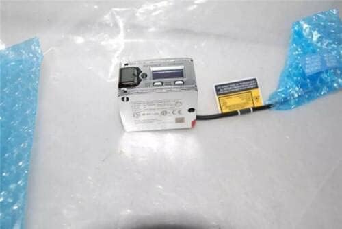
Figure 3.2: The LR-TB5000C Laser Sensor as it appears within its protective bubble wrap packaging, highlighting its compact form factor.
4. Setup
4.1 Unpacking
Carefully remove the sensor and any accessories from the packaging. Inspect all components for any signs of damage. Retain the packaging for future transport or storage.
4.2 Mounting
Mount the LR-TB5000C sensor using the provided mounting bracket and hardware. Ensure the sensor is securely fastened to a stable surface. Position the sensor so that its detection area is clear and unobstructed.
4.3 Wiring
Connect the M12 connector cable to the sensor. Ensure proper polarity for the power supply (20 to 30 VDC). Connect the control output (NPN/PNP open collector) and analog output (current/voltage selectable) to your control system as required. Refer to your system's wiring diagram for specific connections.
5. Operating Instructions
5.1 Powering On
Once wired correctly, apply power to the sensor. The indicator lights on the sensor will illuminate, indicating it is powered on and ready for operation.
5.2 Basic Operation
The LR-TB5000C can detect objects within a range of 60 to 5000 mm. The spot diameter is variable; ensure it is set to 40 mm or less for optimal performance. The sensor uses a red laser (660 nm) for detection.
5.3 Timer Functions
The sensor offers selectable timer functions: OFF, OFF delay, ON delay, and One-shot. Configure these settings via the sensor's interface or connected control system as per your application requirements.
5.4 Mutual Interference Prevention
When using multiple LR-TB5000C sensors in close proximity, enable the mutual interference prevention function. This allows up to 4 units to operate without interference.
6. Maintenance
Regular maintenance ensures optimal performance and longevity of the sensor.
- Cleaning: Periodically clean the lens cover and display with a soft, dry cloth. Avoid abrasive cleaners or solvents.
- Inspection: Check cables and connectors for damage or wear. Ensure mounting hardware remains secure.
- Environmental Conditions: Verify that the operating environment remains within the specified temperature and humidity ranges.
7. Troubleshooting
If the sensor is not functioning as expected, refer to the following common issues and solutions:
- No Power: Check power supply connections and voltage. Ensure the power source is active and within 20-30 VDC.
- No Detection: Verify the sensor's alignment with the target. Check the detectable distance setting. Ensure the lens is clean and unobstructed.
- Incorrect Output: Confirm the NPN/PNP or analog output settings are correct for your control system. Check wiring for continuity and correct connections.
- Interference: If multiple sensors are used, ensure the mutual interference prevention function is enabled.
For persistent issues, contact Keyence technical support.
8. Specifications
Detailed technical specifications for the KEYENCE LR-TB5000C Laser Sensor are provided below.

Figure 8.1: Comprehensive technical specifications for the LR-TB5000C Laser Sensor.
| Specification | Detail |
|---|---|
| Model | LR-TB5000C |
| Type | Cable with connector M12 |
| Detectable Distance | 60 to 5000 mm (2.36" to 196.85") |
| Spot Diameter | Variable (use a spot diameter of 40 mm (1.57") or less) |
| Light Source Type | Red laser (660 nm) |
| Laser Class | Class 2 laser product (IEC60825-1, FDA (CDRH) Part1040.10) |
| Mutual Interference Prevention | 4 units (when using the interference prevention function) |
| Timer | OFF/OFF delay/ON delay/One-shot selectable |
| Response Time | 1 ms/10 ms/25 ms/100 ms/1000 ms selectable |
| Control Output | NPN open collector/PNP open collector selectable, 30 VDC or less, 50 mA or less, residual voltage: 2 V or less, N.O./N.C. selectable |
| Analog Output | Current output/Voltage output selectable. Current: 4 to 20 mA (max. load 500 Ω). Voltage: 0 to 10 V (external load 5 kΩ or more) |
| Protection Circuit | Reverse power connection, power supply surges, output overcurrent, reverse output connection, and output surge |
| Power Voltage | 20 to 30 VDC, including 10% ripple (P-P), Class 2 or LPS |
| Current Consumption | 50 mA or less (without load) |
| Enclosure Rating | IP65/IP67 (IEC60529) |
| Ambient Light | Incandescent lamp/Sunlight: 100,000 lux or less |
| Ambient Temperature | -20 to +55 °C (-4 to 131 °F) (No freezing) |
| Relative Humidity | 35 to 85 % RH (No condensation) |
| Vibration Resistance | 10 to 55 Hz, Double amplitude 1.5 mm (0.06"), 2 hours in each of the X, Y, and Z directions |
| Shock Resistance | 1,000 m/s², 6 times in each of the X, Y, and Z directions |
| Case Material | Zinc die cast (Nickel chrome plating) |
| Indicator Cover & Buttons Material | PES |
| Lens Cover & Display Material | PMMA (scratch-resistant coating specifications) |
| Cable Bushing Material | PBT |
| Cable PVC | PVC |
| M12 Connector Material | TPE, PBT, Nickel-plated brass |
| Weight | Approx. 160 g |
9. Warranty and Support
For warranty information and technical support, please refer to the official Keyence website or contact your local Keyence representative. Keep your purchase records for warranty claims.
Official Keyence Website: www.keyence.com


