
1. Introduction and Product Overview
This manual provides essential information for the safe and effective installation, operation, and maintenance of the FAHKNS 3 Spool 11 GPM Hydraulic Flow Control Valve. This valve is designed for controlling double-acting hydraulic cylinders in various applications, including small tractors, loaders, and log splitters.
Key features include:
- 3 Spools: Allows control of three independent double-acting hydraulic circuits.
- Flow Rate: Supports a maximum flow of 11 Gallons Per Minute (GPM).
- Pressure Rating: Rated for a maximum operating pressure of 3600 PSI.
- Port Types: Features G1/2 type inlet/outlet ports for pressure and tank lines, and SAE 3/8 NPT ports for work lines (A & B).
- Manual Control: Equipped with adjustable relief lever handles for precise manual operation.
- Double-Acting Operation: Configured to operate double-acting hydraulic cylinders.
- Spring Return: All control levers are equipped with a spring return mechanism, automatically returning to the neutral position when released.
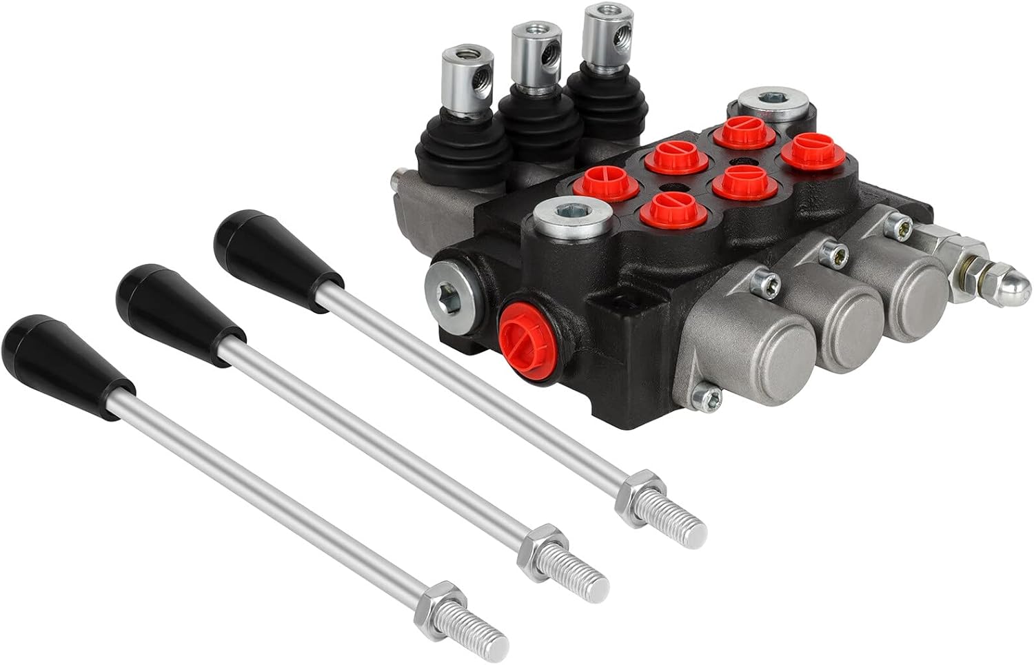
Figure 1.1: FAHKNS 3 Spool 11 GPM Hydraulic Flow Control Valve.
2. Safety Information
Adherence to safety precautions is crucial when working with hydraulic systems. Failure to follow these guidelines can result in serious injury or equipment damage.
- High Pressure Hazard: Hydraulic systems operate under high pressure. Never disconnect hydraulic lines or components without first relieving system pressure.
- Hydraulic Fluid: Hydraulic fluid can cause skin irritation. Use appropriate personal protective equipment (PPE), including gloves and eye protection, when handling hydraulic fluid.
- Pinch Points: Be aware of moving parts and potential pinch points during installation and operation.
- Secure Mounting: Ensure the valve is securely mounted to prevent movement or vibration during operation.
- System Compatibility: Verify that the valve's specifications (pressure, flow, port types) are compatible with your hydraulic system.
- Professional Installation: If you are unfamiliar with hydraulic systems, seek assistance from a qualified professional for installation and setup.
3. Product Components and Identification
Familiarize yourself with the various parts of the hydraulic flow control valve.

Figure 3.1: Key components and port identification.
- Control Levers: Manual levers for directing hydraulic fluid flow.
- Spools: Internal components actuated by the levers to control fluid path.
- Working Orifices (A/B Ports): Ports connecting to the hydraulic cylinder or motor. For this model, these are SAE 3/8 NPT.
- Pressure Port (P): Inlet port for pressurized hydraulic fluid from the pump. This is a G1/2 straight thread o-ring connection.
- Tank Return Port (T): Outlet port for hydraulic fluid returning to the reservoir. This is a G1/2 straight thread o-ring connection.
- Pressure Adjustment: Mechanism to set or adjust the system's relief pressure.

Figure 3.2: Close-up views of valve details.
4. Specifications
Technical specifications for the FAHKNS 3 Spool 11 GPM Hydraulic Flow Control Valve.
| Specification | Value |
|---|---|
| Model | 3 Spool 11 GPM |
| Material | Metal |
| Maximum Operating Pressure | 3600 PSI |
| Maximum Flow Rate | 11 GPM |
| Inlet Connection Type (P Port) | G1/2 Straight Thread O-Ring |
| Tank Return Connection Type (T Port) | G1/2 Straight Thread O-Ring |
| Work Port Connection Type (A/B Ports) | SAE 3/8 NPT |
| Number of Spools | 3 |
| Item Dimensions (L x W x H) | 8.66 x 7.87 x 4.33 inches |
| Item Weight | 14.5 pounds |

Figure 4.1: Product dimensions.
5. Setup and Installation
Proper installation is critical for the safe and efficient operation of the hydraulic valve.
- Mounting: Securely mount the valve to a stable surface on your equipment using appropriate fasteners. Ensure the mounting location allows for easy access to the control levers and hydraulic connections.
- Hydraulic Line Connections:
- Connect the pressure line from your hydraulic pump to the P port (G1/2 straight thread o-ring).
- Connect the tank return line to your hydraulic reservoir to the T port (G1/2 straight thread o-ring).
- Connect the work lines from your hydraulic cylinders or motors to the respective A and B ports for each spool (SAE 3/8 NPT). Ensure correct pairing for desired cylinder movement.
Note: Use appropriate fittings and sealants for each port type to prevent leaks. G1/2 straight thread o-ring connections require specific fittings, while SAE 3/8 NPT ports are tapered pipe threads.
- Fluid System: Ensure the hydraulic system is filled with clean, recommended hydraulic fluid to the correct level. Contaminants can damage the valve and other system components.
- Pressure Relief Adjustment: The valve includes an adjustable pressure relief mechanism. Set the relief pressure according to your system's requirements and component ratings. Consult your equipment's manual for recommended pressure settings.
- Initial Check: Before operating, visually inspect all connections for tightness and ensure there are no obstructions to the control levers.
6. Operation
The FAHKNS hydraulic valve provides manual control over double-acting hydraulic cylinders.

Figure 6.1: Lever positions for operation.
- Neutral Position: When a control lever is in the center position, hydraulic fluid flows through the valve's parallel center circuit back to the tank, and the connected cylinder is held in position. All levers are spring-returned to this position.
- Extend/Retract: Moving a control lever in one direction will direct pressurized fluid to one side of the double-acting cylinder, causing it to extend. Moving the lever in the opposite direction will direct fluid to the other side, causing the cylinder to retract.
- Simultaneous Operation: Due to the parallel oil circuit design, multiple spools can be operated simultaneously, though this may affect the speed and power of individual functions depending on pump capacity.
- Pressure Relief: If system pressure exceeds the set relief valve pressure, fluid will be diverted to the tank, protecting the system from over-pressurization.
7. Maintenance
Regular maintenance ensures the longevity and reliable performance of your hydraulic valve.
- Fluid Quality: Periodically check the hydraulic fluid for contamination and proper level. Replace fluid and filters according to your equipment manufacturer's recommendations.
- Leak Inspection: Regularly inspect all hydraulic connections and the valve body for any signs of leaks. Tighten connections as necessary.
- Cleanliness: Keep the exterior of the valve clean and free from dirt, debris, and corrosive substances.
- Lever Function: Ensure control levers move freely and return smoothly to the neutral position.
8. Troubleshooting
This section addresses common issues that may arise during the operation of the hydraulic valve.
| Problem | Possible Cause | Solution |
|---|---|---|
| No hydraulic function or weak operation | Low hydraulic fluid level, clogged filter, pump malfunction, incorrect pressure setting, air in system. | Check fluid level and add if necessary. Inspect and replace filter. Verify pump operation. Adjust pressure relief valve. Bleed air from the system. |
| Fluid leakage from ports or valve body | Loose connections, damaged seals/o-rings, cracked housing. | Tighten all connections. Inspect and replace damaged seals or o-rings. If housing is cracked, valve replacement may be necessary. |
| Levers do not return to neutral | Damaged return spring, debris obstructing spool movement. | Inspect return springs. Check for and remove any debris around the spool. |
| Erratic or inconsistent cylinder movement | Air in system, contaminated fluid, internal valve issue. | Bleed air from the system. Replace contaminated fluid and filter. If issues persist, consult a hydraulic specialist. |
9. Warranty and Support
For warranty information or technical support, please contact FAHKNS customer service. Keep your purchase receipt and product model information readily available when contacting support.
Contact information can typically be found on the FAHKNS official website or through your original point of purchase.