
1. Introduction
This manual provides detailed instructions for the installation, configuration, and operation of your GIGABYTE H610M H V2 DDR4 Motherboard. This motherboard is designed to support Intel Core 14th, 13th, and 12th generation processors, offering a stable and efficient platform for your computing needs. Please read this manual thoroughly before beginning the installation process to ensure proper setup and to maximize the performance and longevity of your system.
2. Key Features
- Supports Intel Core 14th/ 13th /12th processors (LGA 1700 socket).
- Dual Channel Non-ECC Unbuffered DDR4, 2 DIMMs, supporting up to 3200MHz (OC).
- 6+1+1 Hybrid Digital VRM Design for stable power delivery.
- GbE LAN with Bandwidth Management for reliable network connectivity.
- NVMe PCIe 3.0 x4 M.2 slot for high-speed storage.
- High Quality Audio Capacitors and Audio Noise Guard for enhanced sound.
- Smart Fan 6 features multiple temperature sensors and hybrid fan headers with FAN STOP functionality.
- GIGABYTE APP Center for simple and easy system management.
- Anti-Sulfur Resistors Design for extended durability.
3. Package Contents
Please verify that all items listed below are included in your motherboard package. If any item is missing or damaged, contact your retailer.
- GIGABYTE H610M H V2 DDR4 Motherboard
- SATA Data Cables
- I/O Shield
- User Manual / Quick Installation Guide
- Driver CD/DVD (or link to download drivers)
- M.2 Screw/Standoff Package

Figure 1: GIGABYTE H610M H V2 DDR4 Motherboard and its retail packaging.
4. Setup and Installation
Before installing the motherboard, ensure your power supply is disconnected from the wall outlet. Handle the motherboard by its edges to avoid static discharge.
4.1. Motherboard Layout

Figure 2: Top-down view of the GIGABYTE H610M H V2 DDR4 Motherboard, highlighting component placement.
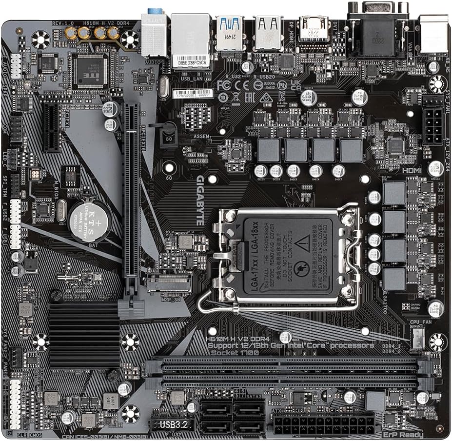
Figure 3: Detailed top-down view of the motherboard, showing various headers and slots.
4.2. CPU Installation (LGA 1700)
- Locate the CPU socket (LGA 1700) on the motherboard.
- Push down the load lever and pull it away from the socket to open the CPU socket cover.
- Carefully align the notches on your Intel LGA 1700 processor with the keys on the socket. Ensure the triangular mark on the CPU aligns with the mark on the socket.
- Gently place the CPU into the socket. Do not force it.
- Close the load plate and push the load lever back into place until it clicks. The plastic cover will pop off automatically.
4.3. RAM Installation (DDR4)
- Locate the two DDR4 DIMM slots.
- Open the clips at both ends of the DIMM slot.
- Align the notch on the DDR4 memory module with the key in the DIMM slot.
- Insert the memory module firmly into the slot until the clips snap into place. Ensure both clips are closed.
- For dual-channel performance, install memory modules into both available slots.
4.4. M.2 SSD Installation
- Locate the NVMe PCIe 3.0 x4 M.2 slot on the motherboard.
- Remove the M.2 standoff screw from the desired length position.
- Insert the M.2 SSD into the slot at a 30-degree angle.
- Push the M.2 SSD down and secure it with the standoff screw.
4.5. Graphics Card and Expansion Cards
- Locate the PCIe x16 slot for your graphics card.
- Open the retention clip at the end of the slot.
- Align your graphics card with the slot and press down firmly until it is fully seated and the retention clip snaps into place.
- For other expansion cards, use the available PCIe x1 slots.
4.6. Power Connections
- 24-pin ATX Main Power Connector: Connect your power supply's 24-pin cable to this connector.
- 8-pin ATX 12V Power Connector: Connect your power supply's 8-pin CPU power cable to this connector.
4.7. Front Panel and Other Connections
Refer to the motherboard layout (Figure 2 and 3) for the exact location of these headers.
- Front Panel Headers: Connect your chassis' power button, reset button, power LED, and HDD LED to the F_PANEL header.
- USB Headers: Connect front panel USB 2.0 and USB 3.2 Gen 1 ports to the corresponding headers.
- Audio Header: Connect your chassis' front panel audio to the F_AUDIO header.
- SATA Ports: Connect SATA storage devices (HDDs/SSDs) to the SATA 6Gb/s ports.
- Fan Headers: Connect CPU fan and system fans to the SYS_FAN and CPU_FAN headers.
4.8. Rear I/O Panel

Figure 4: Rear I/O panel connectors, including USB, video outputs, and audio jacks.
Connect your peripherals to the appropriate ports on the rear I/O panel:
- PS/2 Keyboard/Mouse Port: For legacy keyboard or mouse.
- VGA Port: For display output.
- DVI-D Port: For digital display output.
- HDMI Port: For high-definition digital display output.
- USB 2.0/1.1 Ports: For connecting USB 2.0 devices.
- USB 3.2 Gen 1 Ports: For connecting high-speed USB 3.2 Gen 1 devices.
- RJ-45 LAN Port: For Gigabit Ethernet network connection.
- Audio Jacks: For connecting audio devices (speakers, headphones, microphone).
5. Operating Instructions
5.1. First Boot and BIOS/UEFI Setup
- After assembling your system, connect the power cable and display.
- Press the power button. To enter the BIOS/UEFI setup, repeatedly press the DEL key during startup.
- In the BIOS/UEFI, you can configure boot order, system time, fan speeds, and other hardware settings. Save changes before exiting.
5.2. Driver Installation
After installing your operating system (Windows 10 or Windows 11 recommended), install the necessary drivers for optimal performance.
- Insert the provided driver CD/DVD (if applicable) or download the latest drivers from the official GIGABYTE website (www.gigabyte.com).
- Install chipset drivers, LAN drivers, audio drivers, and any other relevant drivers.
- Utilize the GIGABYTE APP Center for easy driver updates and system utilities.
5.3. Operating System Installation
This motherboard supports Windows 10 and Windows 11 operating systems. Follow the standard installation procedures for your chosen OS.
6. Maintenance
- Dust Removal: Regularly clean dust from inside your PC case, especially around fans and heatsinks, to prevent overheating. Use compressed air.
- BIOS/UEFI Updates: Periodically check the GIGABYTE website for BIOS/UEFI updates. Updates can improve stability, compatibility, and performance. Follow GIGABYTE's instructions carefully when updating the BIOS/UEFI.
- Driver Updates: Keep your drivers updated to ensure optimal system performance and compatibility.
7. Troubleshooting
- No Power:
- Ensure the 24-pin ATX and 8-pin ATX 12V power connectors are securely plugged into the motherboard.
- Check if the power supply is switched on and connected to a working power outlet.
- Verify front panel power button connection.
- No Display:
- Ensure the monitor is connected to the correct video output port (VGA, DVI-D, or HDMI) on the motherboard or graphics card.
- Reseat the graphics card and RAM modules.
- Test with a different monitor or display cable if possible.
- System Instability/Crashes:
- Check RAM modules for proper seating.
- Ensure CPU cooler is properly installed and making good contact with the CPU.
- Verify all power connections.
- Update drivers and BIOS/UEFI to the latest versions.
- Device Not Detected:
- For M.2 SSDs, ensure it is properly seated and secured. Check BIOS/UEFI settings for M.2 slot configuration.
- For SATA devices, ensure data and power cables are securely connected.
- For USB devices, try different USB ports.
8. Specifications
| CPU Socket | LGA 1700 |
| Compatible Processors | Intel Core 14th/13th/12th Gen, Pentium Gold, Celeron |
| Chipset | Intel H610 Express Chipset |
| Memory | 2 x DDR4 DIMM sockets, up to 64 GB, Dual Channel, supports up to 3200 MHz (OC) |
| Expansion Slots | 1 x PCI Express x16 slot (PCIe 4.0), 1 x PCI Express x1 slot (PCIe 3.0) |
| Storage | 1 x M.2 connector (PCIe 3.0 x4), 4 x SATA 6Gb/s connectors |
| LAN | Realtek GbE LAN chip (1 Gbps) |
| Audio | Realtek Audio CODEC, High Definition Audio, 2/4/5.1/7.1-channel |
| USB Ports | 4 x USB 3.2 Gen 1 ports (2 rear, 2 via internal header), 6 x USB 2.0/1.1 ports (4 rear, 2 via internal header) |
| Video Outputs | 1 x D-Sub (VGA), 1 x DVI-D, 1 x HDMI |
| Form Factor | Micro ATX (22.6cm x 21.1cm) |
| Operating System | Windows 11 64-bit, Windows 10 64-bit |
9. Warranty and Support
For detailed warranty information, please refer to the warranty card included with your product or visit the official GIGABYTE website.
If you encounter any issues that cannot be resolved using this manual, please contact GIGABYTE technical support or your local dealer for assistance.
- GIGABYTE Official Website: www.gigabyte.com
- Support Page: Refer to the support section on the GIGABYTE website for drivers, BIOS updates, and FAQs.