
1. Introduction
Thank you for choosing the BSIDE A5X Smart Digital Multimeter. This advanced, rechargeable multimeter is designed for both professional and DIY use, offering a wide range of measurement capabilities with intelligent automatic identification. It features a color LCD display, a built-in rechargeable battery, and a durable design. This manual provides detailed instructions for safe and effective operation of your device.

Figure 1: BSIDE A5X Smart Digital Multimeter and Included Accessories
This image displays the BSIDE A5X Smart Digital Multimeter in its red and black casing, along with its essential accessories. These include red and black test leads, a USB-C charging cable, a thermocouple for temperature measurements, and a protective EVA carrying case. The multimeter features a large color LCD screen showing various measurement modes and readings.
2. Safety Information
To ensure safe operation and service of the meter, follow these instructions. Failure to observe these warnings can result in severe injury or death.
- Always ensure the meter is in the correct function and range for the measurement.
- Do not use the meter if it appears damaged or if the test leads are damaged.
- Do not apply more than the rated voltage, as marked on the meter, between the terminals or between any terminal and earth ground.
- Use extreme caution when working with voltages above 30V AC RMS, 42V peak, or 60V DC. Such voltages pose a shock hazard.
- Keep your fingers behind the finger guards on the test leads during measurements.
- Disconnect the circuit power and discharge all high-voltage capacitors before testing resistance, continuity, diodes, or capacitance.
- Do not operate the meter in explosive gas, vapor, or dust environments.
- Always adhere to local and national safety codes.
3. Package Contents
Verify that all items listed below are included in your package. If any items are missing or damaged, please contact your retailer.
- BSIDE A5X Smart Digital Multimeter
- Test Leads (Red and Black)
- EVA Carrying Case
- Thermocouple
- USB Type-C Charging Cable
- English User Manual
4. Product Features
The BSIDE A5X Multimeter is equipped with a range of features designed for convenience and accuracy:
- Automatic and Easy to Use: Defaults to intelligent mode upon power-on, automatically detecting AC/DC voltage, AC/DC current, resistance, continuity, diode, and frequency. Ideal for beginners.
- Color LCD Display: Inverted color LCD screen with 3 test results: test value, analog bars, and frequency (Hertz). Displays ambient temperature.
- Rechargeable Battery: Built-in 700mA rechargeable Li-ion battery with Type-C charging cable, eliminating the need for disposable batteries.
- Multi-functional: Measures AC/DC voltage, AC/DC current, resistance, capacitance, diode, continuity, frequency, temperature, and duty cycle.
- VFC Function: Measures the output voltage of inverters, useful for planning speeds of pumps, elevators, and air conditioners.
- NCV (Non-Contact Voltage) Detection: High and low sensitivity settings for precise identification of complex lines and easy detection of electrical cables in walls.
- Live/Null Wire Verification: Identifies live and null wires.
- Automatic Range & Auto Power Off: Simplifies operation and conserves battery life.
- Low Battery Indication: Alerts when battery needs recharging.
- Flashlight: Integrated flashlight for working in dark environments.
- Durable Design: Comes with a removable silicone leather case and a robust, shock-resistant EVA case.
5. Specifications
| Parameter | Specification |
|---|---|
| Display | 6000 Counts, 2.2-inch EBTN Color Screen |
| DC Voltage | 0V-620V (0.001V resolution) ±(0.5%+3) |
| AC Voltage | 0V-620V (0.001V resolution) ±(0.5%+5) |
| DC Current | 1.0-610mA (0.1mA resolution) ±(1.5%+3) |
| AC Current | 1.0-610mA (40-1000Hz, 0.1mA resolution) ±(1.5%+3) |
| Resistance | 1Ω-999.9Ω (0.1Ω resolution) ±(2.0%+5); 1kΩ-60MΩ (0.1Ω resolution) ±(1.0%+3) |
| Capacitance | 1nF-999.9nF (0.001nF resolution) ±(6.0%+5); 1uF-99.99mF (0.001nF resolution) ±(3.0%+3) |
| Frequency | 1Hz-1000Hz (0.001Hz resolution) ±(1.0%+5) (ACV: 2V-10V); 1KHz-60KHz (0.001Hz resolution) ±(1.0%+5) (ACV: 10V-620V) |
| Temperature | 0-50℃ (32-122℉) 1℃/1℉ ±(1.5%+2); 50-1000℃ (122-1832℉) 1℃/1℉ ±(2.0%+3) |
| Duty Cycle | 0.1%-99.9% (0.1% resolution) ±(3.0%+5) (ACV: 2V-620V) |
| Diode Test | Auto-identification for diodes below 3.0V |
| NCV Alert | 90V-1000V / 6V-1000V AC Voltage |
| Live Wire Test | Yes |
| Continuity | Resistance below 30Ω, audible buzzer sounds |
| Power Supply | 3.7V Rechargeable Battery |
| Dimensions | 143 x 69 x 17 mm |
| Weight | 125 g |
6. Setup
6.1 Charging the Battery
The BSIDE A5X Multimeter comes with a built-in 700mAh rechargeable Li-ion battery. Before first use, or when the low battery indicator appears, charge the device using the provided USB Type-C cable.
- Connect the USB Type-C end of the charging cable to the multimeter's charging port.
- Connect the USB-A end of the cable to a standard USB power adapter (e.g., phone charger, computer USB port).
- The charging indicator on the multimeter will show the charging status. Once fully charged, the indicator will change (refer to the device's display for specific charging icons).

Figure 2: Charging the Multimeter
This image illustrates the BSIDE A5X Multimeter being charged. The device is shown with its back cover removed, revealing the internal 700mAh Li-ion battery. A USB-C cable is connected to the multimeter and then to a laptop, indicating the charging process. A green battery icon with an arrow suggests the battery is being replenished.
6.2 Connecting Test Leads
Always ensure test leads are securely connected before taking measurements.
- Insert the black test lead into the "COM" (Common) input jack.
- Insert the red test lead into the "VΩHz" input jack for voltage, resistance, frequency, capacitance, diode, and continuity measurements.
- For current measurements (mA), insert the red test lead into the "600mA" input jack.
7. Operating Instructions
7.1 Power On/Off
Press the power button (⑂) to turn the multimeter on or off. The device will automatically enter intelligent mode upon power-on.
7.2 Intelligent Automatic Identification Mode
In intelligent mode, the multimeter automatically identifies and measures AC/DC voltage, AC/DC current, resistance, continuity, diode, and frequency without manual range selection.
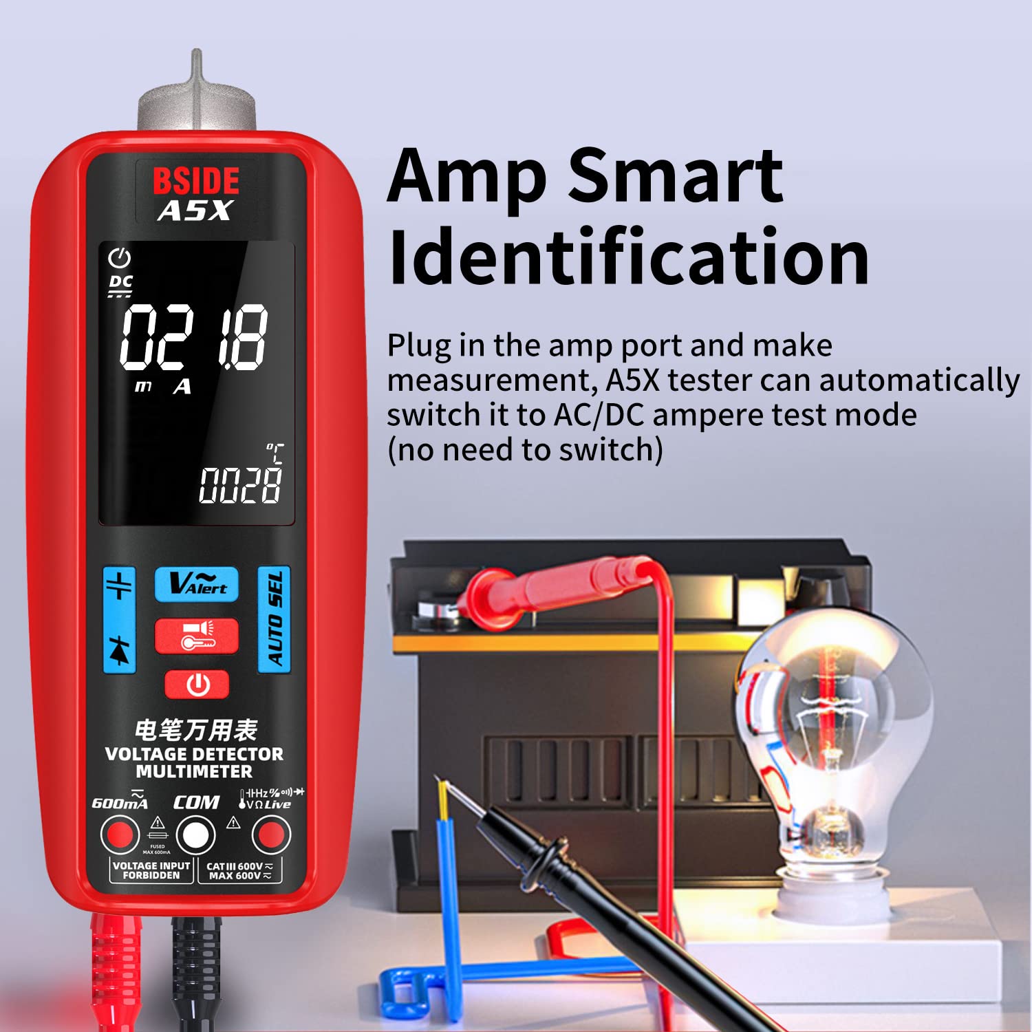
Figure 3: Amp Smart Identification
This image demonstrates the Amp Smart Identification feature of the BSIDE A5X Multimeter. The multimeter is connected to a circuit with a light bulb and a battery. The display shows a current reading in mA, indicating that the device has automatically switched to AC/DC ampere test mode upon connecting the test leads to the amp port, eliminating the need for manual mode selection.
7.3 Manual Mode Selection (Using Buttons)
The multimeter features five buttons for easier function switching. Press the "AUTO SEL" button to cycle through different measurement modes if you wish to manually select a specific function.
7.4 Specific Measurement Modes
7.4.1 Voltage Measurement (AC/DC)
To measure voltage, connect the red test lead to the "VΩHz" jack and the black test lead to the "COM" jack. Apply the test leads across the circuit or component you wish to measure. The meter will automatically detect AC or DC voltage.

Figure 4: AC Voltage Measurement
This image shows the BSIDE A5X Multimeter being used to measure AC voltage within an electrical panel. The display clearly indicates an AC voltage reading of 380.0V and a frequency of 050.0 Hz, demonstrating the device's capability to automatically measure AC voltage and frequency.
7.4.2 Current Measurement (AC/DC)
For current measurements, ensure the red test lead is in the "600mA" jack and the black lead in "COM". Connect the multimeter in series with the circuit. The meter will automatically detect AC or DC current.
7.4.3 Resistance Measurement
Ensure the circuit is de-energized before measuring resistance. Connect the test leads across the component. The meter will automatically display the resistance value.
7.4.4 Capacitance Measurement
WARNING: Before measuring capacitance, ensure the capacitor is fully discharged to prevent damage to the meter or injury.
Connect the test leads across the capacitor terminals. The meter will display the capacitance value.

Figure 5: Capacitance Test
This image shows the BSIDE A5X Multimeter performing a capacitance test on a large cylindrical capacitor. The multimeter's display shows a reading of 31.05 µF, indicating the measured capacitance. A crucial safety reminder is included: "Before measuring capacitance, please discharge the capacitor first."
7.4.5 Frequency Measurement
The meter can measure frequency in AC voltage mode. Connect the test leads to the circuit, and the frequency will be displayed along with the voltage.
7.4.6 Temperature Measurement
Connect the provided thermocouple to the appropriate input jacks (refer to the manual for specific thermocouple connection points, usually marked for temperature). Place the thermocouple probe at the desired measurement point. The display will show the temperature in Celsius or Fahrenheit.

Figure 6: Dual-Way Temperature Test
This image illustrates the BSIDE A5X Multimeter's capability for dual-way temperature measurement. The display shows two temperature readings: "Thermometer Temperature" (0-1000°C / 32-1832°F) and "Environment Temperature" (0-50°C / 32-122°F). The multimeter is shown with a thermocouple probe measuring a component, while the ambient temperature is also displayed.
7.4.7 Diode Test
Ensure the circuit is de-energized. Connect the red test lead to the anode and the black test lead to the cathode of the diode. The meter will display the forward voltage drop. Reverse the leads to check for open circuit.
7.4.8 Continuity Test
Ensure the circuit is de-energized. Connect the test leads across the component or wire. If the resistance is below 30Ω, the audible buzzer will sound, indicating continuity.
7.4.9 NCV (Non-Contact Voltage) Detection
To use NCV, select the NCV mode (if not automatically detected). Hold the top of the multimeter near the wire or outlet. The meter will indicate the presence of AC voltage with visual and audible alerts. Use high sensitivity for detecting wires in walls and low sensitivity for precise identification.
7.4.10 VFC (Variable Frequency Control) Test
The VFC function allows for accurate measurement of output voltage from variable frequency drives (VFDs) or inverters. Select the VFC mode and connect the test leads to the inverter's output.

Figure 7: VFD Test
This image shows the BSIDE A5X Multimeter performing a VFD (Variable Frequency Drive) test. The multimeter is connected to an inverter, and its display shows an AC voltage reading of 220.0V, demonstrating its ability to accurately measure the output voltage of inverters. This function is crucial for assessing the performance of devices like pumps, elevators, and air conditioners.
7.4.11 Live Wire Test
To identify live wires, select the Live Wire Test mode. Place the red test lead into the "Live" input jack (if available, otherwise use NCV or specific live wire detection feature). Touch the probe to the wire. The meter will indicate if the wire is live.

Figure 8: Automotive Circuit Test
This image depicts the BSIDE A5X Multimeter conducting a test on an automotive circuit, specifically connected to a car battery. The display shows a DC voltage reading of 12.8V, indicating the battery's voltage. This demonstrates the multimeter's versatility for use in automotive diagnostics and electrical system checks.
8. Maintenance
8.1 Cleaning
Wipe the case with a damp cloth and mild detergent. Do not use abrasives or solvents.
8.2 Storage
When not in use, store the multimeter in its protective carrying case in a dry, cool place, away from direct sunlight and extreme temperatures. If storing for extended periods, ensure the battery is partially charged (around 50%) to prolong its lifespan.
9. Troubleshooting
| Problem | Possible Cause | Solution |
|---|---|---|
| Meter does not power on. | Low or depleted battery. | Charge the multimeter using the provided USB-C cable. |
| No reading or "OL" displayed. | Open circuit; incorrect range; leads not connected properly. | Check circuit continuity; ensure leads are fully inserted; verify correct measurement mode. |
| Inaccurate readings. | Dirty test leads; external interference; incorrect mode. | Clean test leads; move away from strong electromagnetic fields; ensure correct mode is selected or allow auto-identification. |
| Buzzer not sounding during continuity test. | Resistance is too high (>30Ω); continuity mode not selected. | Check the circuit for breaks; ensure the meter is in continuity mode. |
10. Warranty and Support
The BSIDE A5X Smart Digital Multimeter comes with a standard manufacturer's warranty. Please refer to the warranty card included in your package for specific terms and conditions.
For technical support, troubleshooting assistance, or warranty claims, please contact the seller or manufacturer directly. The product description mentions "technical support in Spanish" which implies direct support from the seller/manufacturer.
- Seller: AIMOmeter-UK (as per buybox_winner.fulfillment.third_party_seller)
- ASIN: B0C3VZ72C4
- Model Number: A5X Rechargeable Automatic Multimeter
Please have your product model number and ASIN ready when contacting support.
