1. Introduction
The MICTUNING P8Y 6-Gang Switch Panel is an advanced auxiliary circuit control system designed for various vehicles including cars, trucks, RVs, and marine applications. It offers versatile control options via Bluetooth RGB APP and a 433MHz RF remote, allowing for convenient management of multiple accessories. This manual provides essential information for the proper installation, operation, and maintenance of your P8Y switch panel.

2. Key Features
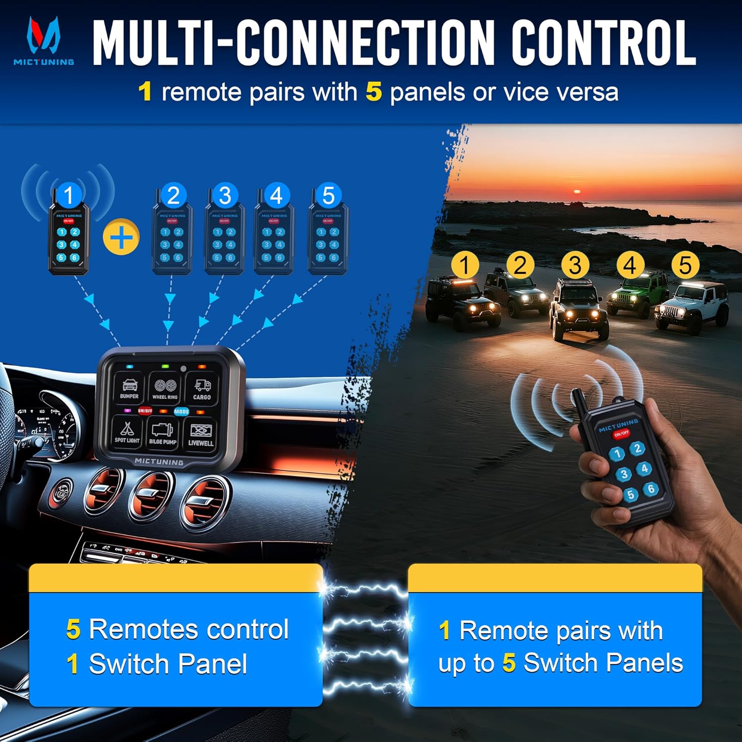
- RF Remote Control: Connects up to 5 RF remote controls with a 230FT (70m) range. One remote can pair with up to 5 power hubs, and one power hub can pair with up to 5 remotes. Features a magnetic back for easy placement.
- IP67 Waterproof Rating: Ensures reliable performance in various weather conditions, suitable for marine, car, RV, truck, and off-road environments.
- Smart Group Control via APP: Supports grouping settings, custom photo album stickers, and notes for easy identification. Offers 4 function operations and 35FT distance control via Bluetooth APP.
- Automatic Dimming & Backlight Off & Memory: Backlight automatically adjusts brightness based on ambient light. Long press the ON/OFF button to turn off the backlight. Memory function restores previous settings after power loss.
- 4 Control Modes with Color Indicators: Features Flash (purple), Toggle (red), Momentary (blue), and Strobe (green) modes, each indicated by a corresponding color for intuitive operation of various accessories.
- Simple Installation & Reliable Safety: Supports loads up to 12V@720W or 24V@1440W (60A max). Operates in extreme temperatures (-40°F to 221°F). Includes comprehensive accessories for installation.
3. Package Contents
Verify that all items listed below are included in your package:
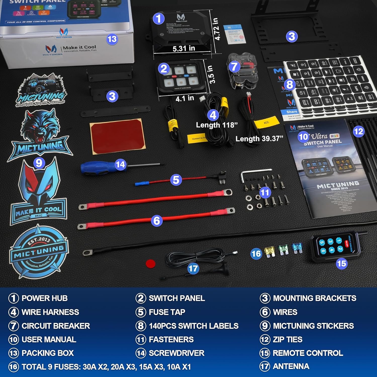
- Power Hub
- Switch Panel
- Mounting Brackets
- Wire Harness
- Fuse Tap
- Wires (Main Power/Ground)
- Circuit Breaker
- 140PCS Switch Labels
- MICTUNING Stickers
- Fasteners
- Zip Ties
- User Manual
- Packing Box
- Screwdriver
- Remote Control
- Total 9 Fuses: 30A x2, 20A x3, 15A x3, 10A x1
- Antenna
4. Technical Specifications
| Specification | Value |
|---|---|
| Brand | MICTUNING |
| Model Number | MIC-P8Y-003 |
| Voltage | 12 Volts (DC) |
| Operating Voltage | 12 Volts |
| Current Rating | 60 Amps (Max) |
| Power Output | 720W@12V or 1440W@24V |
| Operation Mode | ON-OFF-ON |
| Contact Material | Aluminum |
| Item Weight | 4.73 pounds |
| Product Dimensions | 10.62 x 5.9 x 3.54 inches |
| Batteries | 1 Lithium Polymer battery required (included) |
5. Safety Precautions
- Always ensure the vehicle's power is disconnected before installation to prevent electrical shock or damage.
- Strictly adhere to the specified operating voltage (12V DC). Improper voltage may lead to product failure.
- Do not exceed the maximum usage current (60A) for the power hub, as this may cause product failure or fire.
- Ensure all wiring connections are secure and properly insulated to prevent short circuits.
- Mount the power hub and switch panel in locations that are protected from excessive heat and physical damage.
- Use appropriate personal protective equipment (PPE) during installation.
6. Installation Guide
6.1. Wiring Diagram
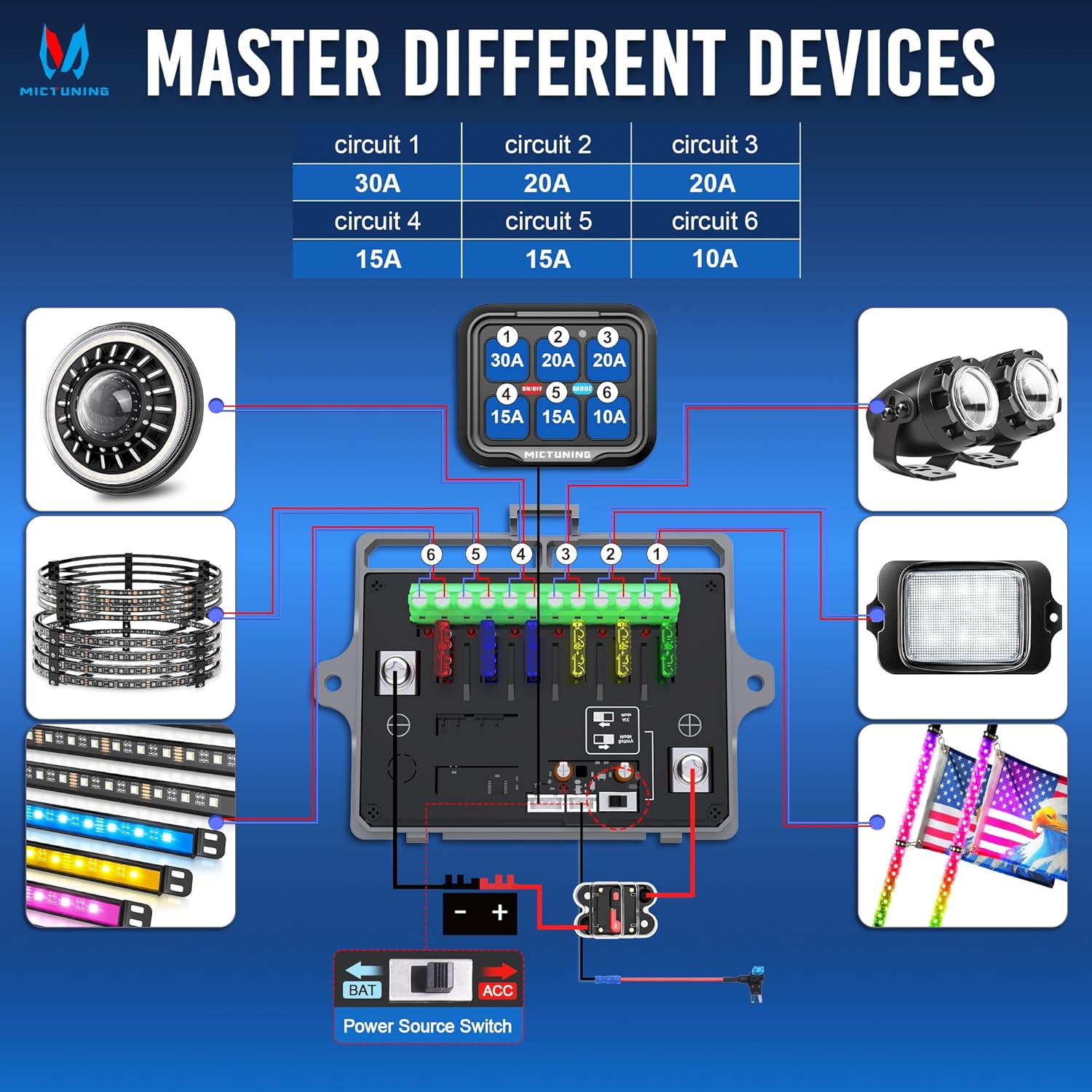
The power hub centralizes wiring for multiple devices, simplifying installation and ensuring a neat setup. Each circuit has a dedicated fuse for protection.
6.2. General Installation Steps
- Mount the Power Hub: Choose a secure, dry location in your vehicle (e.g., engine bay) to mount the power hub using the provided brackets and fasteners. Ensure it is easily accessible for maintenance.
- Connect Main Power: Connect the main positive and negative cables from the power hub to your vehicle's battery terminals. Ensure the circuit breaker is installed on the positive line for safety.
- Connect ACC Wire (Optional): If you desire ignition-controlled power, connect the ACC wire from the power hub to an ignition-switched power source using the provided fuse tap. This allows the system to turn on and off with your vehicle's ignition.
- Mount the Switch Panel: Install the switch panel in a convenient location within your vehicle's cabin using the appropriate mounting brackets.
- Connect Accessories: Connect your auxiliary lights, winches, compressors, fans, etc., to the corresponding fused output terminals on the power hub. Refer to the wiring diagram for circuit capacities (e.g., Circuit 1: 30A, Circuits 2-3: 20A, Circuits 4-5: 15A, Circuit 6: 10A).
- Attach Antenna: Securely attach the antenna to the designated port on the power hub for optimal RF remote range.
- Apply Switch Labels: Use the provided 140PCS switch labels to customize and clearly identify each switch function on the panel.
Video 1: Official MICTUNING P8Y RGB 6 Gang Switch Panel overview and basic setup.
7. Operating Instructions
7.1. RF Remote Control Operation
The P8Y switch panel comes with an RF remote for wireless control up to 230FT (70m).

- Power On/Off: Use the dedicated ON/OFF button on the remote to activate or deactivate the connected accessories.
- Multi-Device Control: One remote can be paired with up to 5 power hubs, or one power hub can be controlled by up to 5 remotes, offering flexible control options.
- Pairing the Remote: To pair the remote, press and hold the pairing button on the power hub until its indicator light blinks slowly. Then, press and hold the power button on the remote. Pairing is successful when the power hub's light turns solid red.
- Clearing Pairing: To clear pairing, press and hold the power hub's pairing button until the light blinks slowly then rapidly. This indicates pairing has been erased.
Video 2: Instructions on how to set up the P8Y Bluetooth RGB & RF Remote switch panel.
7.2. APP Control (Bluetooth RGB)
The MICTUNING P8Y can be controlled via a Bluetooth-enabled smartphone APP, offering advanced customization and control within a 35FT range.

- Connect to APP: Download the MICTUNING APP on your smartphone. Ensure Bluetooth is enabled and connect to your P8Y device.
- Group Settings: Organize and control multiple accessories by creating custom groups within the APP.
- Customization: Add photo album stickers and notes to personalize switch icons and descriptions for easy identification.
- Control Modes: Assign and switch between the 4 control modes (Toggle, Momentary, Flash, Strobe) for each individual switch directly from the APP.
7.3. Backlight Settings
The switch panel features an automatic dimming backlight and customizable RGB colors.

- Automatic Dimming: The backlight automatically dims in dark environments and brightens in well-lit areas to reduce distraction.
- Backlight Off: Long press the ON/OFF button on the switch panel to turn the backlight completely off.
- RGB Color Adjustment: Short press the 'MODE' button on the switch panel to cycle through different backlight colors. The APP also allows for custom color selection and patterns.
7.4. Control Modes
The P8Y offers four distinct control modes for various accessory functions:

- Toggle Mode (Red): Standard on/off function. Press once to turn on, press again to turn off.
- Momentary Mode (Blue): Activates the accessory only while the button is pressed. Releases to turn off. Ideal for horns or temporary functions.
- Flash Mode (Purple): Causes the connected accessory to flash continuously.
- Strobe Mode (Green): Causes the connected accessory to strobe continuously.
8. Maintenance
- Cleaning: Regularly clean the switch panel and power hub with a soft, damp cloth. Avoid abrasive cleaners or solvents.
- Waterproof Integrity: While the system is IP67 waterproof, ensure all connections are sealed and the cover of the power hub is securely fastened to maintain its waterproof rating.
- Fuse Replacement: If an accessory stops working, check the corresponding fuse in the power hub. Replace blown fuses with new ones of the same amperage rating.
- Cable Inspection: Periodically inspect all wiring for signs of wear, fraying, or corrosion. Replace damaged cables immediately.
9. Troubleshooting
- No Power to Panel/Accessories:
- Check main power connections to the battery.
- Verify the circuit breaker is not tripped.
- Ensure the ACC wire (if used) is properly connected and receiving power when the ignition is on.
- Accessory Not Working:
- Check the specific fuse for that circuit in the power hub. Replace if blown.
- Verify the accessory's wiring connection to the power hub.
- Ensure the accessory itself is functioning correctly.
- Remote Control Not Responding:
- Check the remote's battery.
- Re-pair the remote control with the power hub (refer to Section 7.1).
- Ensure there are no obstructions blocking the RF signal.
- APP Connection Issues:
- Ensure Bluetooth is enabled on your smartphone.
- Restart the MICTUNING APP.
- Verify the switch panel is powered on.
- Backlight Not Functioning Correctly:
- Short press the 'MODE' button to cycle through colors.
- Long press the ON/OFF button to toggle the backlight on/off.
- Check APP settings for custom backlight configurations.
10. Warranty and Support
MICTUNING is dedicated to providing innovative and reliable products. The P8Y 6-Gang Switch Panel is manufactured with high-quality standards and features certifications and numerous patents, reflecting our commitment to quality.
For specific warranty details, technical support, or any inquiries regarding your MICTUNING P8Y product, please refer to the contact information provided in your product packaging or visit the official MICTUNING website.


