
1. Introduction
This manual provides essential information for the safe and effective operation of your Jyving MT-3109 AC DC Current Digital Clamp Meter Multimeter. Please read this manual thoroughly before use and retain it for future reference. The MT-3109 is a versatile 3 3/4 digit clamp meter designed for measuring AC/DC voltage, AC/DC current, resistance, capacitance, frequency, and diode testing.
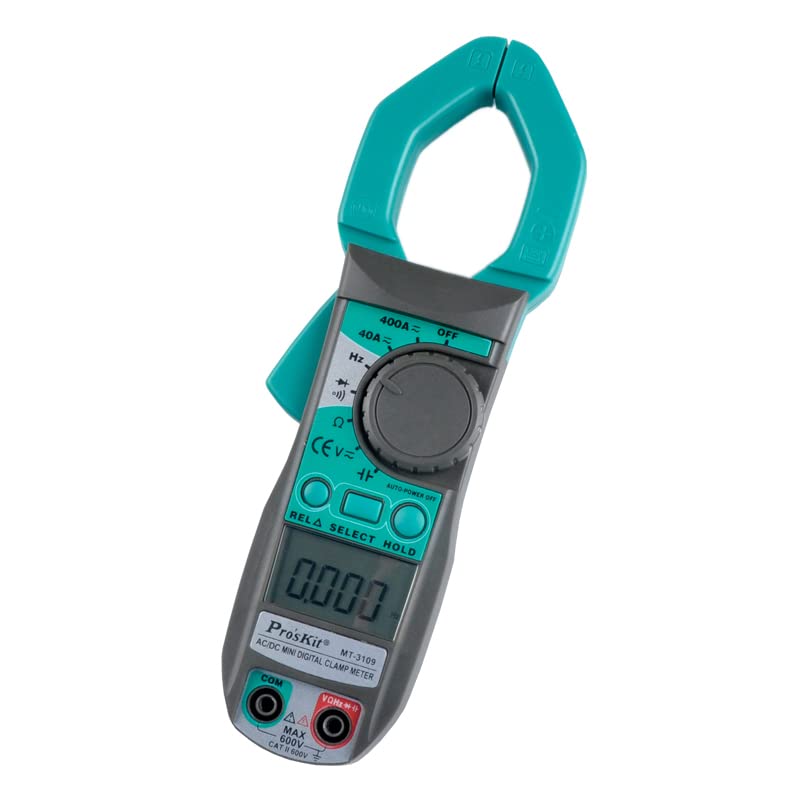
Figure 1: Jyving MT-3109 Digital Clamp Meter Multimeter. This image shows the overall appearance of the clamp meter, featuring its teal clamp jaws, gray body, rotary switch, function buttons, and LCD display.
2. Safety Information
WARNING: To avoid electric shock or personal injury, read and understand all safety information before using this product.
- Always ensure the meter is in good working condition and free from damage before use.
- Do not apply voltage or current that exceeds the maximum rated values specified for the meter.
- Use caution when working with voltages above 30V AC RMS, 42V peak, or 60V DC. These voltages pose a shock hazard.
- Always disconnect the test leads from the circuit before changing functions.
- Replace the battery immediately when the low battery indicator appears to ensure accurate readings.
- Do not operate the meter in explosive gas, vapor, or dusty environments.
- Ensure the clamp jaws are fully closed when measuring current.
3. Product Overview
The MT-3109 clamp meter features a compact design with intuitive controls for various electrical measurements. Key components include:
- Clamp Jaws: Used for non-contact AC/DC current measurement. Maximum jaw opening is 30mm.
- Function Rotary Switch: Selects the desired measurement function (e.g., V~, V-, A~, A-, Hz, Ω, Capacitance, Diode).
- LCD Display: A 3 3/4 digit display with a maximum reading of 3999, showing measurement values and indicators.
- RELA (Relative Value) Button: Used for relative measurement mode.
- SELECT Button: Toggles between different measurement modes within a function (e.g., AC/DC, frequency/duty cycle).
- HOLD Button: Freezes the current reading on the display.
- Input Plugs (COM, VΩHz): For connecting test leads for voltage, resistance, capacitance, frequency, and diode measurements.
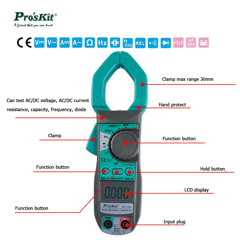
Figure 2: Labeled diagram of the MT-3109 Digital Clamp Meter. This image highlights the main parts of the device, including the clamp, function button, hold button, LCD display, and input plug, along with their respective functions.
4. Setup
4.1 Battery Installation
The MT-3109 requires three AAA (1.5V) batteries (not included) for operation.
- Locate the battery compartment cover on the back of the meter.
- Use a screwdriver to loosen the screw(s) securing the cover.
- Remove the battery compartment cover.
- Insert three AAA 1.5V batteries, observing the correct polarity (+ and -) as indicated inside the compartment.
- Replace the battery compartment cover and tighten the screw(s).
Note: The meter features an automatic shutdown function to conserve battery life. It will also indicate low battery voltage on the LCD display.
5. Operating Instructions
Before taking any measurements, ensure the meter is properly set up and the test leads (if used) are securely connected.
5.1 AC/DC Voltage Measurement
- Set the rotary switch to the V~ (AC Voltage) or V- (DC Voltage) position.
- Insert the black test lead into the COM input jack and the red test lead into the VΩHz input jack.
- Connect the test probes across the circuit or component to be measured.
- Read the voltage value on the LCD display.
5.2 AC/DC Current Measurement (Clamp Method)
- Set the rotary switch to the 40A~ (AC Current) or 400A~ (AC Current) position for AC current, or 40A- (DC Current) or 400A- (DC Current) for DC current.
- Press the trigger to open the clamp jaws.
- Encircle only one conductor of the circuit with the clamp jaws. Ensure the jaws are fully closed.
- Read the current value on the LCD display.
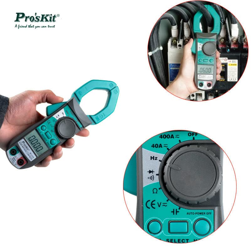
Figure 3: MT-3109 measuring AC current using the clamp function. The image shows the clamp meter's jaws encircling a single conductor to measure current without breaking the circuit.
5.3 Resistance Measurement
- Set the rotary switch to the Ω (Resistance) position.
- Insert the black test lead into the COM input jack and the red test lead into the VΩHz input jack.
- Connect the test probes across the component to be measured. Ensure the circuit is de-energized before measuring resistance.
- Read the resistance value on the LCD display.
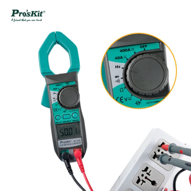
Figure 4: MT-3109 with test leads connected, ready for voltage or resistance measurement. This image illustrates the proper connection of test leads to the input jacks and to a power outlet for measurement.
5.4 Capacitance, Frequency, and Diode Test
For these functions, set the rotary switch to the appropriate position (e.g., Capacitance, Hz, Diode symbol) and use the test leads as described for voltage/resistance measurements. The SELECT button may be used to toggle between frequency and duty cycle measurements if available within the Hz function.
6. Maintenance
6.1 Cleaning
Wipe the case with a damp cloth and mild detergent. Do not use abrasives or solvents. Keep the input terminals free from dirt and moisture.
6.2 Battery Replacement
When the low battery indicator appears on the display, replace the batteries as described in Section 4.1. Remove batteries if the meter is not used for an extended period to prevent leakage.
7. Troubleshooting
- No Display: Check battery installation and ensure batteries are not depleted. Replace if necessary.
- Inaccurate Readings: Ensure correct function selection, proper test lead connection, and that the battery is not low. Verify the measurement range is appropriate for the value being measured.
- "OL" or Overload Indication: The measured value exceeds the selected range. Switch to a higher range or ensure the input is within the meter's maximum specifications.
- No Current Reading (Clamp): Ensure only one conductor is within the clamp jaws. The clamp measures current flowing through a single wire, not a bundled cable.
8. Specifications
| Feature | Specification |
|---|---|
| Display | 3 3/4 digit LCD, Max reading 3999 |
| DC Voltage | 400m/4/40/400/600V |
| AC Voltage | 4/40/400/600V |
| DC Current | 40A, 400A |
| AC Current | 40A, 400A |
| Resistance | 400Ω, 4k/40k/400kΩ, 4MΩ, 40MΩ |
| Capacitance | 40n/400n/4µ/40µ/100µF |
| Frequency | 10/100/1k/10k/100k/1M/10MHz |
| Diode Test | Yes |
| Relative Measurement | Yes |
| Data Hold | Yes |
| Automatic Shift | Yes |
| Short Circuit Buzzer | Yes |
| Low Voltage Indicator | Yes |
| Automatic Shutdown | Yes |
| Accuracy | Up to 1.0% |
| Jaw Opening | Max 30mm |
| Dimensions | 203 x 68 x 33 mm |
| Battery | AAA (1.5V) x 3 pcs (Not included) |

Figure 5: Detailed specifications table for the MT-3109. This image provides a comprehensive list of measurement ranges and features of the clamp meter.
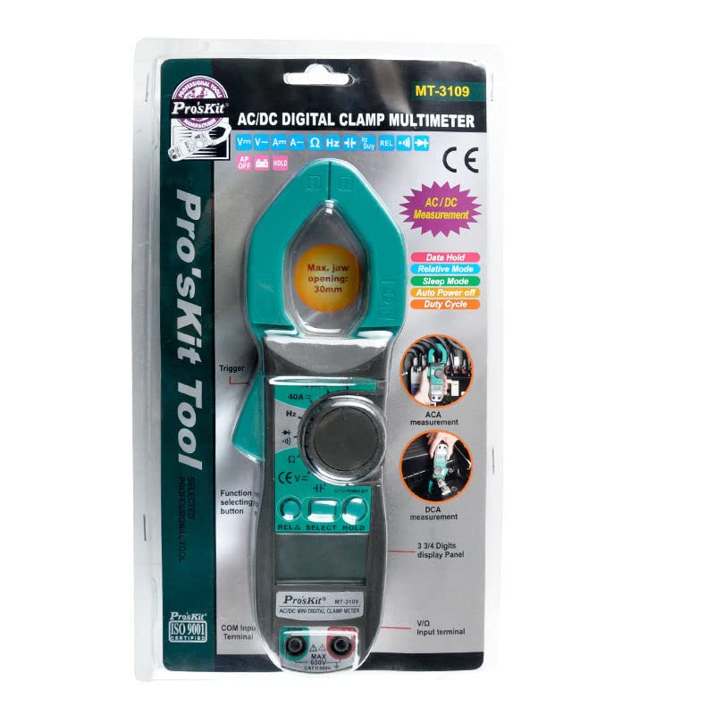
Figure 6: Dimensional drawing of the MT-3109. This image illustrates the physical dimensions of the clamp meter, including its length, width, and thickness.
9. Warranty and Support
For warranty information and customer support, please refer to the documentation provided with your purchase or contact the seller directly. Specific warranty terms may vary by region and retailer.