
Introduction
This manual provides comprehensive instructions for the safe and effective operation of the Jyving MT-1820 Digital Multimeter. The MT-1820 is a 3 5/6 digit, 5999 count multi-function digital multimeter designed for precise electrical measurements. It features both automatic and manual ranging capabilities, a dual display with an analog bargraph, and additional functions such as duty cycle, relative reference, Max/Min hold, data hold, auto power off, and low battery indication.
Please read this manual thoroughly before using the device to ensure proper operation and to prevent potential hazards.
Safety Information
Always adhere to the following safety precautions when using the multimeter:
- Do not exceed the maximum input values specified for each measurement range.
- Ensure the test leads are in good condition, without any cracks or damaged insulation.
- Never use the multimeter if it appears damaged or if the case is open.
- Be cautious when working with voltages above 30V AC RMS, 42V peak, or 60V DC, as these pose a shock hazard.
- Always disconnect power to the circuit and discharge high-voltage capacitors before measuring resistance, continuity, diodes, or capacitance.
- Select the correct function and range before making a measurement.
- Replace batteries immediately when the low battery indicator appears to ensure accurate readings.
Product Overview
The Jyving MT-1820 Digital Multimeter is equipped with various features to facilitate accurate and versatile measurements.

Figure 1: Front view of the Jyving MT-1820 Digital Multimeter, showing the display, rotary switch, and input jacks.
Key Features:
- 3 5/6 Digits, 5999 Counts: Provides high resolution for precise measurements.
- 0.5% Best Accuracy: Ensures reliable measurement results.
- Auto/Manual Ranging: Offers flexibility for different measurement scenarios.
- Dual Display with Analog Bargraph: Allows for simultaneous display of numerical and analog readings.
- USB Connectivity: Enables data upload to a PC for monitoring and recording.
- Additional Functions: Includes Duty Cycle, Relative Reference, Max/Min Hold, Data Hold, Auto Power Off, and Low Battery Indication.
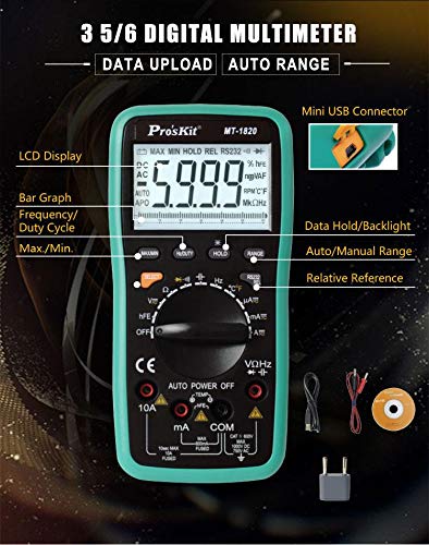
Figure 2: An annotated diagram highlighting key components and features of the MT-1820 Multimeter, including the LCD display, bar graph, frequency/duty cycle, Max/Min, Mini USB Connector, Data Hold/Backlight, Auto/Manual Range, and Relative Reference functions.
Setup
Battery Installation:
- Locate the battery compartment cover on the back of the multimeter.
- Use a screwdriver to remove the screw securing the cover.
- Insert two 1.5V AAA batteries, observing the correct polarity (+ and -).
- Replace the battery compartment cover and secure it with the screw.
Note: Batteries are not included in the package.
Initial Checks:
- Ensure the test leads are securely plugged into the correct input jacks.
- Verify that the rotary switch is set to the OFF position when not in use.
Operating Instructions
This section details how to perform various measurements using the MT-1820 Digital Multimeter.

Figure 3: Visual examples demonstrating how to perform DC Voltage, AC Voltage, Continuity, Temperature, and Capacitance measurements using the multimeter.
1. Measuring DC Voltage (DCV):
- Insert the red test lead into the "VΩHz" jack and the black test lead into the "COM" jack.
- Turn the rotary switch to the "V=" position.
- Connect the test leads across the component or circuit to be measured, observing polarity.
- Read the DC voltage value on the display.
2. Measuring AC Voltage (ACV):
- Insert the red test lead into the "VΩHz" jack and the black test lead into the "COM" jack.
- Turn the rotary switch to the "V~" position.
- Connect the test leads across the AC voltage source.
- Read the AC voltage value on the display.
3. Measuring DC Current (DCA):
- For currents up to 600mA, insert the red test lead into the "mA" jack. For currents up to 10A, insert the red test lead into the "10A" jack. Insert the black test lead into the "COM" jack.
- Turn the rotary switch to the "mA=" or "10A=" position.
- Open the circuit and connect the multimeter in series with the load.
- Read the DC current value on the display.
4. Measuring AC Current (ACA):
- For currents up to 600mA, insert the red test lead into the "mA" jack. For currents up to 10A, insert the red test lead into the "10A" jack. Insert the black test lead into the "COM" jack.
- Turn the rotary switch to the "mA~" or "10A~" position.
- Open the circuit and connect the multimeter in series with the load.
- Read the AC current value on the display.
5. Measuring Resistance (Ω):
- Insert the red test lead into the "VΩHz" jack and the black test lead into the "COM" jack.
- Turn the rotary switch to the "Ω" position.
- Ensure the circuit is de-energized. Connect the test leads across the resistor or component.
- Read the resistance value on the display.
6. Continuity Test:
- Insert the red test lead into the "VΩHz" jack and the black test lead into the "COM" jack.
- Turn the rotary switch to the "Continuity" position (often represented by a sound wave or speaker symbol).
- Touch the test leads across the circuit or component. A continuous beep indicates a good connection (low resistance).
7. Diode Test:
- Insert the red test lead into the "VΩHz" jack and the black test lead into the "COM" jack.
- Turn the rotary switch to the "Diode" position (often represented by an arrow with a bar symbol).
- Connect the red lead to the anode and the black lead to the cathode of the diode. The display will show the forward voltage drop. Reverse the leads; the display should show "OL" (Open Loop) for a good diode.
8. Capacitance Measurement:
- Insert the red test lead into the "VΩHz" jack and the black test lead into the "COM" jack.
- Turn the rotary switch to the "Capacitance" position (often marked with a capacitor symbol).
- Ensure the capacitor is fully discharged before connecting the test leads.
- Connect the test leads across the capacitor.
- Read the capacitance value on the display.
9. Temperature Measurement:
- Connect the temperature probe (thermocouple) to the appropriate input jacks (usually marked "TEMP" or with a temperature symbol).
- Turn the rotary switch to the "TEMP" position (often °C/°F).
- Place the tip of the temperature probe on or near the object whose temperature is to be measured.
- Read the temperature value on the display.
10. USB Data Upload:
The MT-1820 features a Mini USB connector for data transfer to a computer.
- Connect the multimeter to your PC using a compatible USB cable.
- Install the provided software (if applicable, usually on a mini-CD or available for download).
- Follow the software instructions to monitor, record, and analyze measurement data.

Figure 4: The MT-1820 Multimeter connected via USB to a laptop, demonstrating its data upload capability for monitoring and recording measurements.
Maintenance
Cleaning:
Wipe the case with a damp cloth and mild detergent. Do not use abrasives or solvents. Ensure the device is off and disconnected from any circuits before cleaning.
Battery Replacement:
When the low battery indicator appears on the display, replace the batteries as described in the "Setup" section. Always use fresh 1.5V AAA batteries.
Fuse Replacement:
If the current measurement function fails, the fuse may need replacement. Refer to the specifications for the correct fuse type and rating. Fuse replacement should only be performed by qualified personnel.
Troubleshooting
- No Display: Check battery installation and ensure batteries are not depleted.
- "OL" or "Open Loop" on Display: This usually indicates an open circuit, a measurement exceeding the range, or incorrect lead connection for resistance/continuity/diode tests.
- Inaccurate Readings: Ensure correct function and range are selected. Check battery level. Verify test leads are properly connected and not damaged.
- Current Measurement Not Working: Check the fuse. Ensure the multimeter is connected in series with the circuit.
Specifications
The following table outlines the technical specifications of the Jyving MT-1820 Digital Multimeter.

Figure 5: Detailed technical specifications table for the MT-1820 Multimeter, including ranges and accuracies for DCV, ACV, DCA, ACA, Resistance, Frequency, Capacitance, and Temperature, along with continuity, diode, and transistor test capabilities, power source, and dimensions.
| Measurement Type | Range & Accuracy |
|---|---|
| DCV | 600m/6/60/600V ±(0.5%+5d), 1000V ±(1.0%+6d) |
| ACV | 6/60/600V ±(0.8%+10d), 750V ±(1.0%+10d) |
| DCA | 600μ/6000μA ±(1.0%+10d), 60m/600mA ±(1.0%+10d), 6/10A ±(1.2%+10d) |
| ACA | 600μ/6000μA ±(1.5%+10d), 60m/600mA ±(1.5%+10d), 6/10A ±(2.0%+10d) |
| Resistance | 600Ω ±(0.8%+5d), 6k/60k/600k/6MΩ ±(0.8%+4d), 60MΩ ±(1.2%+10d) |
| Frequency | 100/1000Hz ±(0.5%+5d), 10k/100kHz ±(0.5%+4d), 1M/30MHz ±(0.5%+4d) |
| Capacitance | 40mF ±(5%+30d), 400n/4μ/40μF ±(3.5%+8d), 200μF ±(5.0%+10d) |
| Temperature | -20~400°C(0~750°F) ±(1.0%+5d), 400~1000°C(750~1832°F) ±(1.5%+10d) |
| Continuity with buzzer | Yes |
| Diode test | Yes |
| Transistor test | Yes |
| Power source | AAA(1.5V)×2pcs (Not Included) |
| Size | 192×95×48 mm |
| Individual Packing | Color box |
Warranty and Support
The Jyving MT-1820 Digital Multimeter comes with a standard manufacturer's warranty against defects in materials and workmanship. For specific warranty terms and conditions, please refer to the documentation included with your purchase or contact Jyving customer support.
For technical assistance, troubleshooting, or to inquire about replacement parts, please contact Jyving customer service through their official website or the contact information provided with your product.