1. Introduction
Thank you for choosing the K&F CONCEPT X-Series 68" Carbon Fiber Camera Tripod (Model X284C4+BH-36). This professional photography tripod is designed for stability, portability, and versatility, suitable for both indoor and outdoor use. Featuring a 36mm metal ball head and carbon fiber construction, it offers a robust solution for various photographic needs. This manual provides detailed instructions for proper setup, operation, maintenance, and troubleshooting to ensure optimal performance and longevity of your tripod.
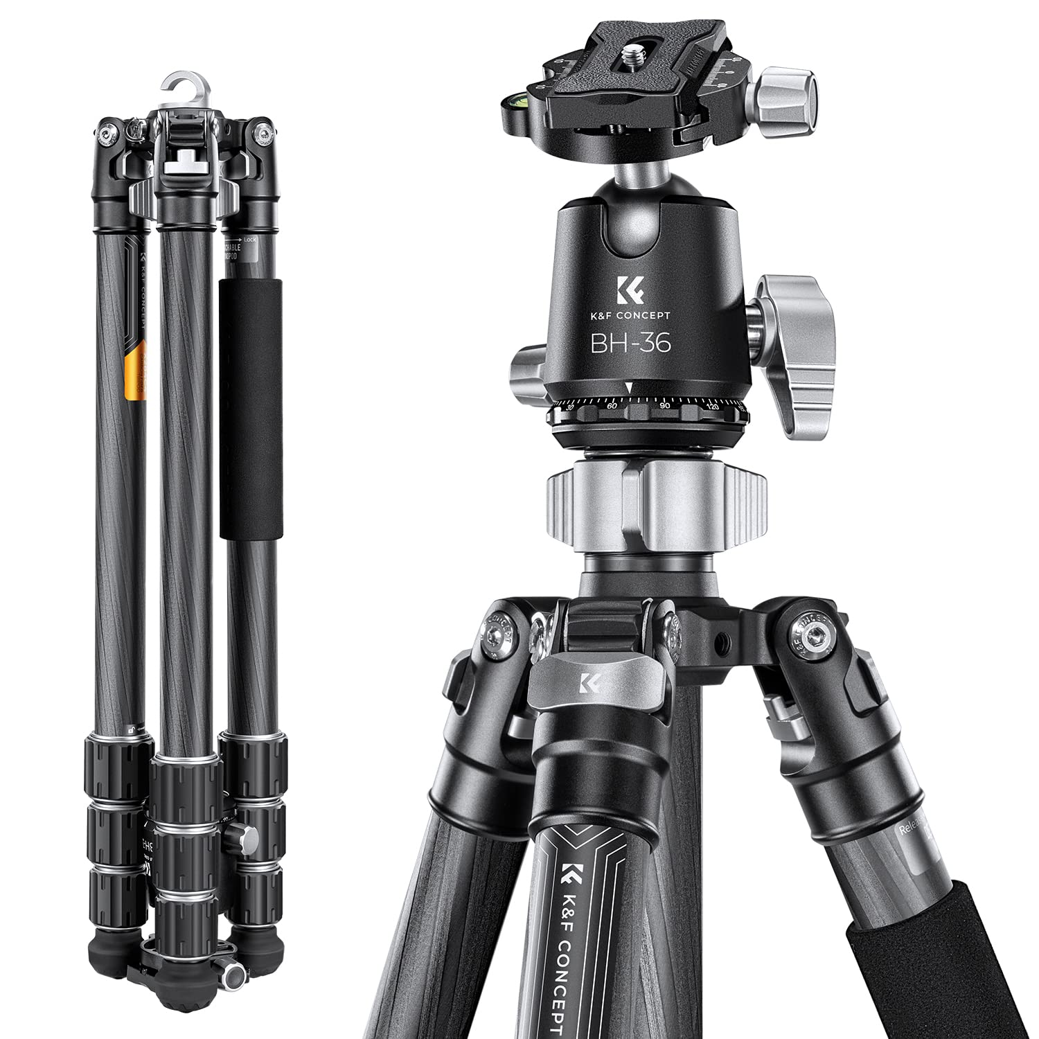
Image 1.1: The K&F CONCEPT X-Series Carbon Fiber Camera Tripod, Model X284C4+BH-36, showcasing its design and key specifications like leg sections, tube diameter, max height, folded length, load capacity, and weight.
2. Setup Guide
2.1 Unpacking and Initial Inspection
Carefully remove all components from the packaging. Verify that all parts listed in the packing list are present and undamaged. The package typically includes the tripod, BH-36 ball head, carrying bag, and a hex wrench set.

Image 2.1: Contents of the K&F CONCEPT tripod package, including the tripod, ball head, carrying bag, and accessories.
2.2 Extending the Tripod Legs
The tripod features 4-section carbon fiber legs. To extend a leg, twist the leg locks counter-clockwise to loosen, pull out the desired section, and then twist clockwise to secure. Repeat for all leg sections and all three legs. Ensure all leg locks are firmly tightened before mounting equipment.

Image 2.2: Close-up view of the tripod leg sections, illustrating the twist-lock mechanism for extension and retraction. The tripod has a maximum load capacity of 16kg.
2.3 Attaching the Ball Head
The BH-36 metal ball head comes pre-attached to the tripod. If it needs re-attaching or tightening, ensure the tripod's mounting screw (typically 3/8 inch) aligns with the ball head's base. Rotate the ball head clockwise until it is securely fastened. Use the included hex wrench to tighten the anti-loose screws on the ball head base for enhanced stability.

Image 2.3: Detailed view of the BH-36 metal ball head, highlighting its 36mm diameter, CNC machining, and various knobs for adjustment.
2.4 Mounting Your Camera
Attach the quick release plate to the bottom of your camera using the 1/4 inch screw. Ensure it is tightened securely. Open the quick release plate locking knob on the ball head, align the plate with the clamp, and slide it in. Close the locking knob firmly to secure your camera. Always double-check the camera's stability before letting go.
2.5 Adjusting Leg Angles
Each leg can be independently adjusted to three different angles. Press the angle adjustment tab at the top of each leg to change its position. This allows for stable setup on uneven terrain or for achieving various shooting heights.

Image 2.4: Close-up of the tripod leg hinge, demonstrating the mechanism for adjusting leg angles to three different positions.
3. Operating Instructions
3.1 Panoramic Shooting
The BH-36 ball head features a 360-degree panoramic base. Loosen the panoramic knob (the smallest knob at the base of the ball head) to rotate the camera smoothly for panoramic shots. Tighten the knob to lock the position.

Image 3.1: A camera mounted on the tripod, demonstrating the 360-degree panoramic rotation capability of the ball head for capturing wide landscape shots.
3.2 Overhead Shooting
To achieve overhead shots, extend the center column fully and adjust the leg angles to provide maximum stability. The ball head allows for precise angling of the camera downwards. Ensure the tripod is on a stable surface and the load is balanced.

Image 3.2: The tripod configured for overhead shooting, with the center column extended and camera pointed downwards, ideal for product photography or top-down views.
3.3 Low-Angle Shooting
For low-angle photography, spread the tripod legs to their widest angle. This brings the camera closer to the ground. The ball head's flexibility allows for precise framing even at very low positions.
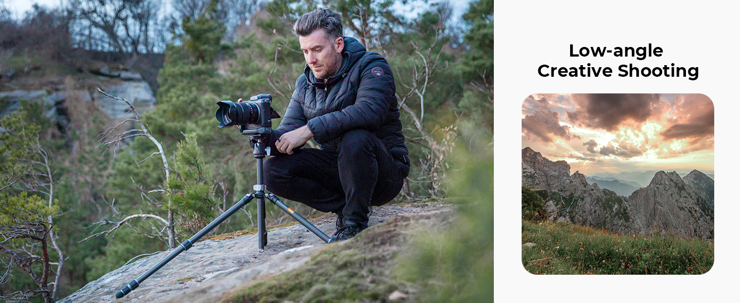
Image 3.3: A photographer using the tripod in a low-angle configuration, demonstrating its ability to capture subjects from a ground-level perspective.
3.4 Inverted Shooting
To achieve inverted shooting, remove the center column, invert it, and reinsert it into the tripod's main chassis. Mount the ball head and camera to the inverted column. This technique is useful for extreme low-angle shots or macro photography.

Image 3.4: The tripod set up for inverted shooting, with the center column reversed to allow the camera to hang below the tripod's base, ideal for macro photography near the ground.
3.5 Detachable Monopod Function
One of the tripod legs can be detached and combined with the center column to form a monopod. Unscrew the designated leg from the tripod body. Unscrew the center column from the main chassis. Attach the detached leg to the center column. The ball head can then be mounted onto the monopod for handheld stability.

Image 3.5: Illustration showing how one of the tripod legs can be detached and combined with the center column to create a monopod for versatile shooting options.
3.6 Interchangeable Foot Nails
The tripod feet feature a standard 3/8 inch interface, allowing for easy switching between rubber feet and optional long foot nails (purchased separately). This provides enhanced grip on various terrains like soft ground or ice.

Image 3.6: Close-up view of the tripod foot, demonstrating the 3/8 inch standard interface for attaching different types of foot nails, such as rubber feet or spiked feet.
3.7 Product Video Overview
Video 3.7: An official product video from K&F Concept showcasing the features and usage of the X-Series Carbon Fiber Camera Tripod in various outdoor settings, including setup, adjustments, and different shooting modes.
4. Maintenance
4.1 Cleaning
- Carbon Fiber Legs: Wipe down carbon fiber legs with a soft, damp cloth after each use, especially if exposed to dirt, sand, or saltwater. Avoid abrasive cleaners.
- Metal Components: Clean metal parts, including the ball head and leg locks, with a dry or slightly damp cloth. Ensure no moisture remains in moving parts.
- Lubrication: Periodically check the smoothness of leg extension and ball head movement. If necessary, apply a small amount of silicone-based lubricant to the leg sections or ball head mechanism, avoiding excessive application.
4.2 Storage
Store the tripod in its carrying bag in a dry, cool place, away from direct sunlight and extreme temperatures. Ensure the tripod is clean and dry before storage to prevent corrosion or damage.
5. Troubleshooting
5.1 Tripod Instability
- Issue: Tripod feels wobbly or unstable.
- Solution: Ensure all leg section locks are fully tightened. Verify that the leg angle adjustment tabs are securely engaged. Check if the camera is properly mounted and balanced on the quick release plate.
5.2 Ball Head Movement Issues
- Issue: Ball head does not hold position or is difficult to move.
- Solution: Ensure the main locking knob for the ball head is tightened sufficiently. If movement is stiff, clean the ball and socket area and apply a minimal amount of lubricant if needed. If the quick release plate is loose, ensure its locking knob is fully engaged and the camera is securely attached to the plate.
5.3 Leg Sections Sticking
- Issue: Leg sections are difficult to extend or retract.
- Solution: Loosen the twist locks completely. Clean any dirt or debris from the leg sections and inside the locking mechanisms. If necessary, apply a small amount of silicone lubricant to the sliding surfaces.
6. Specifications
| Feature | Detail |
|---|---|
| Model Number | KF09.117 (X284C4+BH-36) |
| Material | Carbon Fiber, Aluminum |
| Maximum Height | 1725 mm (68 inches) |
| Minimum Height | 585 mm |
| Folded Length | 58.5 cm (23 inches) |
| Leg Sections | 4 |
| Tube Diameter | 28 mm |
| Load Capacity | 16 kg (35.2 lbs) |
| Item Weight | 1.76 kg (3.87 lbs) |
| Tripod Head Type | Ball Head (BH-36) |
| Ball Head Diameter | 36 mm |
| Compatible Devices | Camera (DSLR, Mirrorless, Projector, Telescope, etc.) |
| Special Features | Adjustable, Compact, Rotatable, Detachable Monopod |
7. Warranty & Support
7.1 Warranty Information
K&F CONCEPT products are manufactured to high-quality standards and come with a limited warranty against defects in materials and workmanship. Please refer to the warranty card included with your product or visit the official K&F CONCEPT website for detailed warranty terms and conditions.
7.2 Customer Support
For technical assistance, product inquiries, or warranty claims, please contact K&F CONCEPT customer support through their official website or the contact information provided in your product packaging. When contacting support, please have your product model number (X284C4+BH-36) and purchase details readily available.