
BSIDE A5 Smart Multimeter
BSIDE A5 Smart Digital Multimeter User Manual
Model: A5 Smart Multimeter
Product Overview
The BSIDE A5 Smart Digital Multimeter is a new generation professional electrical multimeter designed for both electricians and beginners. It features an intelligent auto-ranging mode, a large backlit LCD display, and multiple measurement functions.

Image: The BSIDE A5 Smart Digital Multimeter shown with its test leads, thermocouple, AAA batteries, and carrying case.
Key Features
- Automatic and Simple Operation: Defaults to smart mode, automatically adjusting to the measurement type for quick and accurate readings.
- Multi-functional Performance: Measures AC/DC voltage, AC/DC current, resistance, capacitance, diode, continuity, frequency, temperature, and features NCV detection with adjustable sensitivity.
- Large Detailed Display: Intuitive large number interface with 3 test results: test value, analog bars, and ambient temperature/hertz. The screen turns red if tested voltage exceeds 90V.
- Inverter Voltage Measurement (VFC): Capable of measuring the output voltage of inverters, useful for planning speeds of pumps, elevators, air conditioners, compressors, etc.
- Portable Design: Compact, pocket-sized multimeter with a durable zippered carrying case and a bright LED flashlight for testing in dark conditions.
- Safety Features: High impedance design protects against burns and overloads.
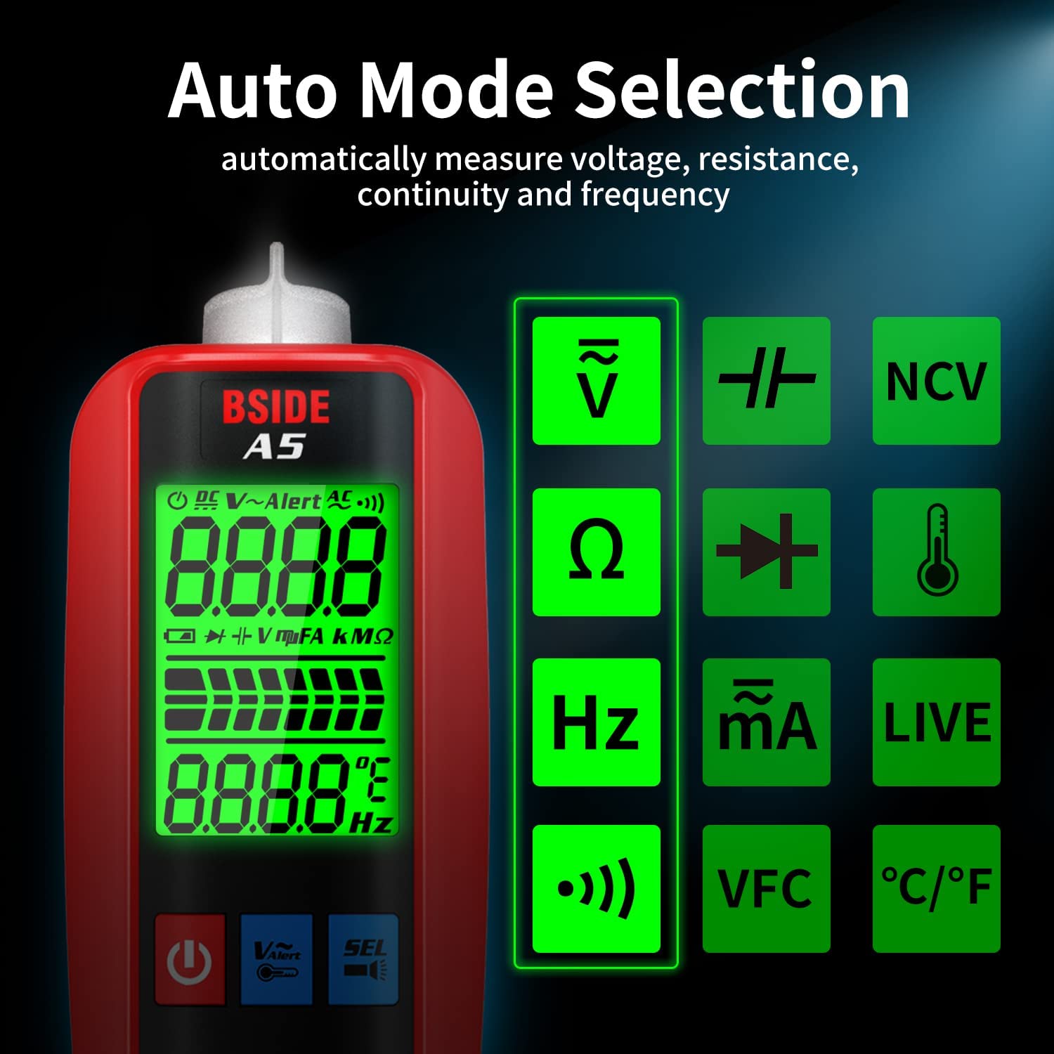
Image: The BSIDE A5 Multimeter display showing various measurement modes available in auto mode, including NCV, Resistance, Frequency, Current, Diode, Temperature, Continuity, VFC, and Celsius/Fahrenheit.
Package Contents
Upon opening the package, please verify that all items listed below are present and in good condition:
- Multimeter Tester (BSIDE A5)
- Test Leads (Red and Black)
- Thermocouple
- Carrying Case (EVA)
- 2 x AAA Batteries
- Screwdriver
- English Manual (This document)
Setup
1. Battery Installation
- Locate the battery compartment on the back of the multimeter.
- Use the provided screwdriver to open the battery cover.
- Insert the 2 AAA batteries, ensuring correct polarity (+/-).
- Close the battery cover and secure it with the screw.
2. Connecting Test Leads
- For most measurements (Voltage, Resistance, Continuity, Diode, Frequency, Capacitance, Temperature), insert the red test lead into the "VΩHz" input jack and the black test lead into the "COM" input jack.
- For current measurements (mA), insert the red test lead into the "600mA" input jack and the black test lead into the "COM" input jack.

Image: The BSIDE A5 Multimeter demonstrating current measurement. The red test lead is connected to the 600mA input port, and the black lead to the COM port, measuring current for a light bulb circuit.
Operating Instructions
1. Power On/Off
Press the Power button () to turn the multimeter on or off. The device features an auto power-off function to conserve battery life.
2. Smart Mode (Default)
Upon powering on, the multimeter enters Smart Mode. In this mode, it automatically identifies and measures AC/DC voltage, resistance, continuity, and frequency without manual range selection.
3. Manual Mode Selection
Press the SEL button to cycle through different manual measurement modes (e.g., Diode, Capacitance, Temperature, VFC, NCV, Live Wire Check). The selected mode will be indicated on the display.
4. Specific Measurement Functions
- Voltage Measurement (AC/DC): In Smart Mode, connect test leads across the circuit. For VFC (Variable Frequency Control) voltage, select VFC mode via the SEL button.

Image: The BSIDE A5 Multimeter displaying a VFC measurement, showing its capability to measure the output voltage of an inverter.
- Current Measurement (AC/DC): Ensure the red test lead is in the "600mA" input jack. The A5 automatically switches to AC/DC ampere test mode when connected correctly.
- Resistance Measurement: In Smart Mode, connect test leads across the component.
- Continuity Test: In Smart Mode, if resistance is below 50Ω, an audible beep will sound.
- Diode Test: Select Diode mode via the SEL button. Measures diodes less than 3V.
- Capacitance Measurement: Select Capacitance mode via the SEL button.
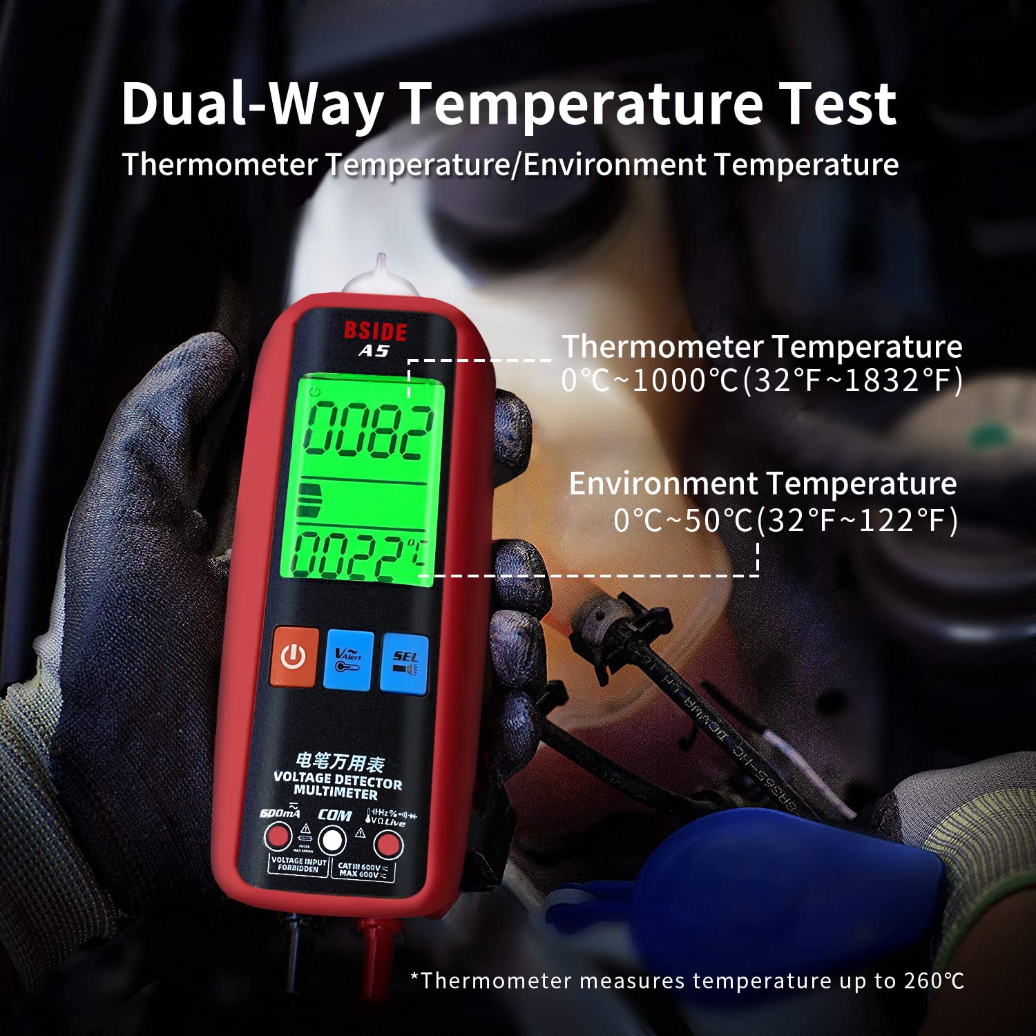
Image: The BSIDE A5 Multimeter measuring the capacitance of a large capacitor, demonstrating its use in electronic maintenance.
- Frequency Measurement: In Smart Mode, the frequency will be displayed.
- Temperature Measurement: Select Temperature mode via the SEL button. Use the provided thermocouple. The display shows both thermometer temperature and ambient temperature.

Image: The BSIDE A5 Multimeter displaying both thermometer temperature (top) and environment temperature (bottom), illustrating its dual-way temperature measurement capability.
- NCV (Non-Contact Voltage) Detection: Press the V~Alert button. The device will detect AC voltage without contact. Sensitivity is adjustable.

Image: A hand holding the BSIDE A5 Multimeter near an electrical panel, demonstrating its non-contact voltage detection (V~Alert) feature.
- Live Wire Check: Select Live Wire Check mode via the SEL button.
5. Display Features
- Backlit LCD: The display features a red/green backlight for improved visibility. The screen turns red when voltage exceeds 90V.

Image: The BSIDE A5 Multimeter display showing both green (low voltage) and red (high voltage) backlight states, indicating its visual alert system.
- Analog Bar Graph: Provides a quick visual indication of the measured value.
Maintenance
1. Cleaning
Wipe the multimeter with a dry, soft cloth. Do not use abrasive cleaners or solvents. Ensure the device is powered off before cleaning.
2. Battery Replacement
When the low battery indicator appears on the display, replace the AAA batteries promptly to ensure accurate readings. Follow the battery installation steps in the "Setup" section.
3. Storage
Store the multimeter in its carrying case in a cool, dry place, away from direct sunlight and extreme temperatures. Remove batteries if storing for extended periods to prevent leakage.
Troubleshooting
| Problem | Possible Cause | Solution |
|---|---|---|
| Multimeter does not power on. | Dead or incorrectly installed batteries. | Check battery polarity. Replace batteries if necessary. |
| Inaccurate readings. | Low battery, incorrect mode selection, or damaged test leads. | Replace batteries. Ensure correct mode is selected for the measurement. Inspect test leads for damage. |
| No continuity beep. | Resistance is above 50Ω, or continuity mode not selected. | Ensure the circuit resistance is below 50Ω. Verify continuity mode is active (Smart Mode or manual selection). |
| Display shows "OL" (Overload). | Measurement exceeds the multimeter's range. | Ensure the measurement is within the specified range for the selected function. |
Specifications
| Parameter | Value |
|---|---|
| Display | 6000 counts, 2.2 inches LCD |
| DC Voltage | 0-620V (DC mode) / 0.8-620V (Auto mode) ±(0.8%+3) |
| AC Voltage | 0-620V (DC mode) / 0.8-620V (Auto mode) ±(1.2%+5); 10-620V (VFC mode) ±(4.0%+3) |
| DC Current | 1.0-610mA ±(1.5%+3) |
| AC Current | 1.0-610mA (40-1000Hz) ±(1.5%+3) |
| Resistance | 0Ω-6MΩ ±(1.2%+3); 6MΩ-60MΩ ±(2.0%+10) |
| Capacitance | 0.5µF-6mF ±(3.5%+8); 6mF-60.00mF ±(4.5%+10) |
| Frequency | 0-9999Hz (900mVrms-20Vrms) ±(2.0%+10) |
| Temperature | 0-50℃ (32-122℉) ±(1.5%+2); 50-1000℃ (122-1832℉) ±(2.0%+3) |
| V-Alert (NCV) | Yes |
| Diode Test | Measures diodes less than 3V |
| Continuity | Audible beep if resistance < 50Ω |
| Live Wire Check | Yes |
| Ambient Temperature | 0-50℃ ±2℃ |
| Power Supply | 2 x 1.5V AAA batteries |
| Dimensions | 139.7 x 53.7 x 32.8 mm |
| Weight | 92g |
| Safety Compliance | CE |
Safety Information
Always observe basic safety precautions when using this multimeter to avoid personal injury or damage to the device. Read all instructions before use.
- Do not exceed the maximum input values for any function.
- Do not use the multimeter if it or the test leads appear damaged.
- Be cautious when working with voltages above 30V AC RMS, 42V peak, or 60V DC. These voltages pose a shock hazard.
- Always disconnect the test leads from the circuit before changing functions.
- Ensure the correct function and range are selected for the measurement.
- Do not operate the multimeter in explosive gas, vapor, or dust environments.
- Replace batteries immediately when the low battery indicator appears.
Warranty and Support
For warranty information and technical support, please refer to the contact details provided by your retailer or visit the official BSIDE website. Keep your purchase receipt as proof of purchase.
This product is designed for reliable performance. If you encounter any issues not covered in the troubleshooting section, please contact customer support for assistance.
Related documentsA5 Smart Multimeter


Ask a question about this manual
Ask about setup, troubleshooting, compatibility, parts, safety, or missing instructions. Manuals+ will review the question and use this page’s manual context to help answer it.