Introduction
This manual provides essential information for the proper installation, operation, and maintenance of the POTTER PAD 100-DIM Dual Input Module. Please read these instructions thoroughly before attempting to install or operate the device. Retain this manual for future reference.
Safety Information
WARNING: This device is part of a fire safety system. Improper installation or maintenance can compromise the system's effectiveness, potentially leading to property damage, serious injury, or death. Installation and servicing must be performed by qualified personnel in accordance with all national and local codes and regulations.
- Always disconnect power before installing, servicing, or removing the module.
- Ensure all wiring connections are secure and comply with wiring diagrams and local electrical codes.
- Do not expose the module to moisture or extreme temperatures.
- Refer to the control panel's manual for compatibility and system integration details.
Product Overview
The POTTER PAD 100-DIM is a dual input module designed for use with compatible fire alarm control panels. It allows for the monitoring of two independent dry contact initiating device circuits (IDCs) from a single addressable point on the signaling line circuit (SLC).
Key Features
- Monitors two independent initiating device circuits.
- Addressable communication with the fire alarm control panel.
- Designed for integration into fire safety systems.
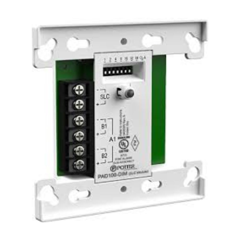
Figure 1: Front view of the POTTER PAD 100-DIM Dual Input Module. This image shows the compact design of the module, typically housed in a protective casing, with visible terminals for wiring connections.
Setup and Installation
Installation of the PAD 100-DIM module should only be performed by a certified fire alarm technician. Refer to the specific wiring diagrams provided with the module and the fire alarm control panel for detailed connection instructions.
- Power Disconnection: Ensure all power to the fire alarm control panel and associated circuits is disconnected before beginning installation.
- Mounting: Mount the module in a suitable electrical enclosure, ensuring adequate ventilation and protection from environmental factors.
- SLC Connection: Connect the Signaling Line Circuit (SLC) wires from the control panel to the designated terminals on the PAD 100-DIM module. Observe polarity.
- IDC Connections: Connect the two independent Initiating Device Circuits (IDCs) to their respective input terminals on the module. Ensure proper end-of-line resistor (EOLR) placement as specified by the control panel manufacturer.
- Addressing: Set the module's address using the rotary switches or dip switches, as applicable, to match the address programmed in the fire alarm control panel.
- Verification: After all connections are made, verify wiring integrity and then restore power to the control panel.
- System Test: Conduct a full system test in accordance with NFPA 72 and local codes to confirm proper operation of the module and connected devices.
Operating Instructions
The PAD 100-DIM module operates by continuously monitoring the status of its two connected Initiating Device Circuits (IDCs). When an event (e.g., alarm, trouble) occurs on an IDC, the module communicates this status change to the fire alarm control panel via the Signaling Line Circuit (SLC).
- Normal Operation: In a normal state, the module continuously monitors the connected IDCs for open, short, or alarm conditions.
- Alarm Condition: Upon detection of an alarm condition on an IDC, the module transmits an alarm signal to the control panel.
- Trouble Condition: Detection of an open or short circuit on an IDC will result in a trouble signal being sent to the control panel.
- LED Indicators: (If applicable, consult specific product documentation for LED behavior) Typically, an LED on the module will indicate normal operation (e.g., flashing green) and alarm/trouble conditions (e.g., steady red or amber).
All operational status and events are displayed and managed at the main fire alarm control panel.
Maintenance
Regular maintenance is crucial for the reliable operation of any fire safety equipment. All maintenance procedures should be performed by qualified fire alarm technicians.
- Annual Inspection: Conduct annual inspections of the module and its connections as part of the overall fire alarm system inspection.
- Visual Check: Inspect the module for any signs of physical damage, corrosion, or loose connections.
- Functional Testing: Periodically test the connected initiating devices to ensure the module correctly reports alarm and trouble conditions to the control panel.
- Cleaning: If necessary, gently clean the exterior of the module with a soft, dry cloth. Do not use abrasive cleaners or solvents.
- Record Keeping: Maintain detailed records of all inspections, tests, and maintenance performed.
Troubleshooting
If the PAD 100-DIM module or its connected circuits are not functioning as expected, refer to the following troubleshooting steps. For complex issues, contact a qualified fire alarm technician.
- No Power/Communication:
- Verify that the fire alarm control panel is powered on and the SLC is active.
- Check SLC wiring for breaks, shorts, or incorrect polarity.
- Ensure the module's address is correctly set and matches the control panel programming.
- IDC Trouble Condition:
- Inspect the wiring of the affected IDC for opens or shorts.
- Verify the correct end-of-line resistor (EOLR) is installed at the last device on the circuit.
- Test the initiating devices connected to the IDC for proper operation.
- False Alarms:
- Check for environmental factors affecting initiating devices (e.g., dust, steam for smoke detectors).
- Ensure proper wiring and grounding to prevent electrical interference.
- Verify the integrity of the initiating devices themselves.
Always consult the fire alarm control panel's manual for specific trouble codes and diagnostic procedures.
Specifications
| Attribute | Value |
|---|---|
| Brand | POTTER |
| Model Number | PPAD100DIM |
| Part Number | PPAD100DIM |
| Item Package Quantity | 1 |
| UPC | 737214686880 |
| Date First Available | May 25, 2022 |
Warranty and Support
For warranty information, technical support, or service inquiries regarding the POTTER PAD 100-DIM Dual Input Module, please contact your authorized POTTER distributor or the manufacturer directly. Keep your purchase receipt and product model number (PPAD100DIM) available when contacting support.
Manufacturer: POTTER
For further assistance, visit the official POTTER website or consult your fire safety system installer.