
Introduction
This manual provides detailed instructions for the setup, operation, and maintenance of your Makerbase MKS TS35 V1.0 LCD Display Panel. The MKS TS35 is a 3.5-inch color touch screen display designed for 3D printers, offering a user-friendly interface, real-time monitoring, and offline printing capabilities. It is compatible with Makerbase MKS Robin Nano and MKS Gen_L series boards.
1. Setup and Wiring
This section guides you through the physical installation and wiring of the MKS TS35 V1.0 LCD Display Panel with a compatible mainboard, such as the MKS Robin Nano V3.0. Ensure all power is disconnected before proceeding with any wiring.
1.1 Mainboard Overview
The MKS Robin Nano V3.0 mainboard features various ports for stepper motor drivers, power, heaters, fans, and endstops. Its dimensions and hole patterns are compatible with previous versions like Nano V2 and Gen_L, simplifying upgrades.

Figure 1: MKS Robin Nano V3.0 Mainboard with installed stepper motor drivers.
1.2 Display Panel Overview
The MKS TS35 V2.0 display panel connects to the mainboard via ribbon cables and features a rotary knob and reset button.

Figure 2: MKS TS35 V2.0 LCD Display Panel.
1.3 Wiring Steps
- Install Motor Drivers: Carefully insert the stepper motor drivers into their designated slots on the MKS Robin Nano V3.0 mainboard. Ensure correct orientation.
- Connect Power Supply: Connect the main power supply wires (red for positive, black for negative) to the power input terminals on the mainboard. Secure the connections using a screwdriver.
- Connect Heated Bed: Attach the heated bed power wires to the appropriate terminals on the mainboard.
- Connect Extruder Heater: Connect the extruder heater wires to its designated terminals.
- Connect Fan, Extruder Thermal, and Heated Bed Thermal: Connect the fan, extruder thermistor, and heated bed thermistor wires to their respective ports.
- Connect Uncontrollable Fan & Motor: Connect any uncontrollable fans and motors as required by your 3D printer setup.
- Connect X/Y/Z Endstops: Connect the X, Y, and Z axis endstop switches to their corresponding ports on the mainboard.
- Connect MKS TS35 Touch Screen: Connect the ribbon cables from the MKS TS35 display panel to the TFT screen ports on the mainboard. Ensure the cables are securely seated.
Video 1: Detailed wiring instructions for the MKS Robin Nano V3 with MKS TS35 Display on an Ender 3 machine.
2. Firmware Update
The MKS Robin Nano V3.0 mainboard typically comes with pre-flashed firmware. However, it is recommended to update to the latest version for optimal performance and features. You can either use pre-compiled firmware or compile it yourself from the source code.
2.1 Using Pre-compiled Firmware
- Download Firmware: Obtain the latest pre-compiled firmware for MKS Robin Nano V3.0 from the official Makerbase GitHub repository. Look for the `Robin_nano__v3.bin` file and the `assets` folder.
- Prepare USB Disk/TF Card: Format a USB disk or TF card (FAT32 format is usually required).
- Copy Files: Copy the `Robin_nano__v3.bin` file and the `assets` folder to the root directory of the USB disk or TF card.
- Insert and Update: With the mainboard powered off, insert the USB disk or TF card into the designated slot on the MKS Robin Nano V3.0 mainboard. Power on the mainboard. The display will show an "Updating..." message, indicating the firmware is being flashed. Once complete, the system will restart.
2.2 Compiling Firmware from Source Code (Advanced Users)
For advanced users who wish to customize their firmware, you can download the source code and compile it using Visual Studio Code with PlatformIO extension.
- Download Source Code: Download the Marlin firmware source code for MKS Robin Nano V3.0 from the Makerbase GitHub repository.
- Open in Visual Studio Code: Open the downloaded firmware folder in Visual Studio Code.
- Configure `platformio.ini`: Open the `platformio.ini` file. Modify the `default_envs` setting to `mks_robin_nano_v3_usb_flash_drive_msc`.
- Configure `Configuration.h`: Open the `Configuration.h` file (located in `Marlin/src/Marlin`).
- Set `#define MOTHERBOARD` to `BOARD_MKS_ROBIN_NANO_V3`.
- Enable `#define SERIAL_PORT 3`.
- Enable `#define MKS_TS35_V2_0` for the display.
- Enable `#define TFT_LVGL_UI` for the LVGL user interface.
- Enable `#define TOUCH_SCREEN`.
- Adjust endstop inversion settings (e.g., `#define X_MIN_ENDSTOP_INVERTING true` if needed).
- Adjust stepper direction settings (e.g., `#define INVERT_X_DIR true` if needed).
- Set `X/Y/Z_HOME_DIR` to `-1`.
- Compile Firmware: Use the PlatformIO extension in Visual Studio Code to compile the modified firmware.
- Update Mainboard: Copy the compiled `.bin` file and `assets` folder to a USB disk/TF card and update the mainboard as described in section 2.1.
3. Operation
The MKS TS35 V1.0 LCD Display Panel provides an intuitive touch interface for controlling your 3D printer. After successful firmware update and power-on, the display will show the main menu.
3.1 User Interface
The 3.5-inch color touch screen features a responsive interface with a rotary knob for navigation and selection. The interface can be customized with different themes and layouts, including LVGL-UI, Classic-UI, and Color-UI, depending on your firmware configuration.

Figure 3: MKS TS35 V2.0 display showing language selection, supporting multiple languages.
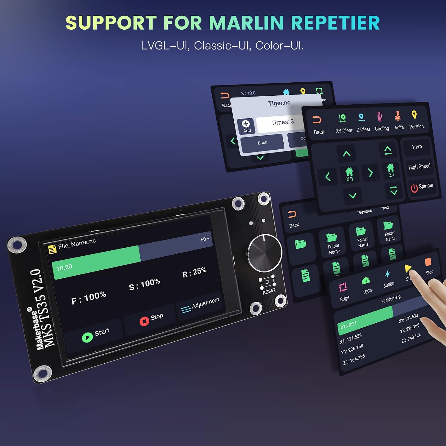
Figure 4: MKS TS35 V2.0 display showing file preview and printing options.
3.2 Printing from SD Card
The MKS TS35 supports offline printing directly from an SD card. Simply save your G-code files to the SD card, insert it into the mainboard's TF card slot, and select the desired file from the display's interface to begin printing.
3.3 Real-time Monitoring
During printing, the display provides real-time monitoring of the printing process, including status, progress, temperatures, and other relevant information. This allows for immediate adjustments and oversight of your print jobs.
4. Key Features
- 3.5-inch Color Touch Screen Display: Easy to use and navigate interface for controlling your 3D printer.
- Compatibility: Fully compatible with Makerbase MKS Robin Nano series and MKS Gen_L series boards.
- Real-time Monitoring: Displays status, progress, and other relevant information during the printing or machining process.
- Offline Printing: Enables printing directly from an SD card without requiring a connected computer.
- Customizable Interface: Allows for personalization with logos, icons, and backgrounds to suit user preferences.
- Easy Installation: Designed for straightforward installation, typically mounting on the front of the machine.
- Compact Design: Space-saving design that minimizes the footprint on your machine.
- Responsive Touch Screen: Provides a responsive and intuitive touch experience for machine control.
5. Specifications
| Color | Black |
| Brand | Makerbase |
| Voltage | 5 Volts |
| Display Type | Touchscreen |
| Model | MKS TS35 Touch Screen |
| Included Components | MKS TS35 Color Display |
6. Troubleshooting
If you encounter issues with your MKS TS35 V1.0 LCD Display Panel, please consider the following common troubleshooting steps:
- Display Not Powering On: Verify all power connections to the mainboard and ensure the power supply is functioning correctly. Check the ribbon cable connections between the display and the mainboard.
- Touch Screen Unresponsive: Ensure the firmware is correctly installed and configured for touch screen operation. Re-calibrate the touch screen if the option is available in your firmware settings.
- Firmware Update Failure: Double-check that the firmware file (`.bin`) and `assets` folder are copied to the root directory of a properly formatted (FAT32) USB disk or TF card. Ensure the correct firmware version for your specific mainboard and display is used.
- Printing Issues: Confirm that your G-code files are valid and compatible with your printer's settings. Check filament loading and nozzle temperature.
- Communication Errors: If using a serial connection, verify the baud rate settings in your firmware match your host software.
For further assistance, refer to the online resources provided in the Support & Resources section.
7. Support & Resources
For additional support, firmware downloads, and community discussions, please refer to the following official Makerbase resources:
- Official Makerbase Website: Visit the Makerbase Store on Amazon
- GitHub Repository (MKS Robin Nano V2.x): MKS Robin Nano V2.x Display User Guide
- GitHub Repository (MKS SGEN_L V1.0 and V2.0): MKS SGEN_L V1.0/V2.0 MKS TS35 User Guide
- Makerbase YouTube Channel: Official Makerbase YouTube Channel
- Makerbase GitHub Profile: Makerbase GitHub Repositories
- Makerbase Facebook Page: Makerbase Official Facebook Page
- MKS TS35 User Guide (QR Code Link): MKS TS35 User Guide
8. Warranty Information
Please refer to the retailer or the official Makerbase website for specific warranty terms and conditions applicable to the MKS TS35 V1.0 LCD Display Panel. Keep your proof of purchase for any warranty claims.