
1. Introduction
This manual provides detailed instructions for the safe and efficient operation of your Kiprim DC310S Programmable DC Power Supply. Please read this manual thoroughly before use and keep it for future reference. The Kiprim DC310S is a high-precision, programmable DC power supply designed for various applications including testing, repair, research, laboratory work, and DIY projects. It features a 0-30V, 0-10A output, a 4-digit display, multiple protection functions, low noise operation, and smart cooling.
2. Safety Instructions
To ensure safe operation and prevent damage to the device or injury, observe the following safety precautions:
- Always connect the power cord protective grounding conductor to ground.
- Do not operate the device in wet or damp conditions.
- Do not remove covers. Refer servicing to qualified personnel only.
- Ensure proper ventilation to prevent overheating.
- Verify input voltage compatibility before connecting to a power source.
- Avoid connecting the power supply directly to batteries without proper current limiting or charging circuits, as this may damage the power supply or battery.
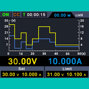
Image: Warning against directly connecting the power supply to a battery without appropriate charging circuits.
3. Product Features
- Multiple Protections: Features Over-Voltage Protection (OVP) up to 31V, Over-Current Protection (OCP) up to 10.1A, and Over-Temperature Protection (OTP) at 85°C. Includes intelligent fan cooling. OVP and OTP limits are user-settable.
- Multi-functional Display: Equipped with a 2.8-inch color LCD. Displays set and actual output voltage, set and actual output current, actual output power, accumulated run time, channel output status, and OVP/OCP settings. The DISPLAY key allows switching between numerical and graphical (curve) data views. Rated output voltage: 0-30V; Rated output current: 0-10A. Set/Readback Resolution: Voltage: 10mV; Current: 1mA. Set/Readback Accuracy: Voltage: ≤0.1%±20mV; Current: ≤0.1%±10mA.
- Programmable Power Supply: The memory function allows saving 4 sets of channel parameters (M1-M4) for quick recall and output. Waveform output settings enable users to edit and output custom waveforms. Each waveform set includes 10 editable points, with parameters for output voltage, output current, waveform duration, and point selection. After editing, the device outputs the waveform according to the user-defined sequence. Supports automatic output settings upon startup.
- Dual USB Ports: Includes a rear USB interface for program upgrades and PC control, and a front 5V 1A USB interface for charging mobile devices. Note: Supports USB Type-C and Micro USB (Android charging ports). Lightning interfaces are not supported.
4. Package Contents
Verify that all items are present in the package:
- 1 x Kiprim DC310S Variable DC Power Supply (30V/10A)
- 1 x User Manual
- 1 x Fuse
- 1 x Banana-to-Alligator Clip Cable
- 1 x Power Cable
- Software (downloadable from https://bit.ly/37Bwt92, CD not included in some regions)
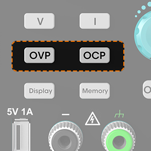
Image: The Kiprim DC310S power supply, user manual, cables, and fuse included in the package.
5. Product Overview and Function Description
Familiarize yourself with the components and controls of the DC310S power supply.

Image: Detailed diagram showing the front and rear panels of the Kiprim DC310S, with labels for all buttons, ports, and indicators.
Front Panel Controls and Indicators:
- Display Area: 2.8-inch color LCD for displaying voltage, current, power, time, and settings.
- Voltage Setting Key (V): Press to adjust voltage.
- Current Setting Key (I): Press to adjust current.
- Over Voltage Setting Key (OVP): Press to set over-voltage protection limit.
- Over Current Setting Key (OCP): Press to set over-current protection limit.
- Memory Button: Used to save and recall parameter settings (M1-M4).
- Display Switch Button: Toggles between numerical and graphical display modes.
- USB Charging Port (5V 1A): For charging mobile devices.
- Voltage/Current Adjust Knob: Rotary encoder for fine-tuning voltage and current values.
- On/Off Key: Toggles the output of the power supply.
- Channel Output Terminals (+/-): Red for positive, Black for negative output.
- Ground Strap: Green terminal for grounding.
Rear Panel Components:
- Cooling Fan: Automatically activates to dissipate heat.
- AC Power Input: Connects to the main power cable.
- Power Switch: Main power switch for the unit.
- Fuse Box: Contains the replaceable fuse for circuit protection.
- Device USB Port: For PC connection, software upgrades, and remote control.
6. Setup
- Unpacking: Carefully remove the power supply and all accessories from the packaging. Inspect for any signs of damage.
- Placement: Place the power supply on a stable, level surface with adequate ventilation. Ensure the cooling fan at the rear is not obstructed.
- Power Connection: Connect the provided power cable to the AC Power Input on the rear panel and then to a suitable AC power outlet (100-120V AC).
- Initial Power On: Flip the main Power Switch on the rear panel to the 'ON' position. The display should illuminate.
- Output Connection: Connect your load to the Channel Output Terminals (+ for positive, - for negative) using the banana-to-alligator clip cable or other appropriate cables. Ensure correct polarity.
7. Operating Instructions
7.1 Basic Voltage and Current Setting
- Ensure the main power switch is ON.
- Press the 'V' button to select voltage adjustment. The voltage value on the display will blink.
- Rotate the Voltage/Current Adjust Knob to set the desired output voltage.
- Press the 'I' button to select current adjustment. The current value on the display will blink.
- Rotate the Voltage/Current Adjust Knob to set the desired output current limit.
- Press the 'On/Off' button to enable the output. The output indicator will light up.
- To disable the output, press the 'On/Off' button again.
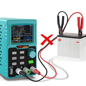
Image: Close-up of the 'On/Off' button, used to enable or disable the power output.
7.2 Over-Voltage Protection (OVP) and Over-Current Protection (OCP)
The DC310S includes OVP and OCP features to protect your connected devices.
- Press the 'OVP' button. The OVP value on the display will blink.
- Rotate the Voltage/Current Adjust Knob to set the desired maximum voltage limit. If the output voltage exceeds this limit, the output will shut down.
- Press the 'OCP' button. The OCP value on the display will blink.
- Rotate the Voltage/Current Adjust Knob to set the desired maximum current limit. If the output current exceeds this limit, the output will shut down.
- Press the 'OVP' or 'OCP' button again to confirm the setting.
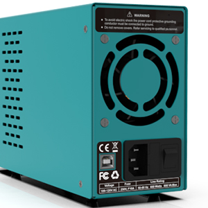
Image: Close-up of the OVP and OCP buttons on the front panel, used for setting protection limits.
8. Programmable Features
8.1 Memory Function (M1-M4)
The power supply allows you to save and quickly recall up to 4 sets of frequently used voltage and current parameters.
- Set the desired voltage and current using the 'V' and 'I' buttons and the adjust knob.
- Press and hold the 'Memory' button until a memory slot (M1-M4) blinks.
- Rotate the adjust knob to select the desired memory slot (M1, M2, M3, or M4).
- Press the 'Memory' button again to save the current settings to the selected slot.
- To recall a saved setting, briefly press the 'Memory' button, select the desired slot, and press 'Memory' again.

Image: Display showing the M1-M4 memory slots with saved voltage, current, OVP, and OCP parameters.
8.2 Waveform Output Settings
The DC310S supports editing and outputting custom waveforms with up to 10 editable points. Refer to the detailed software manual (downloadable from the provided link) for comprehensive instructions on creating and executing waveforms via PC control.
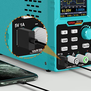
Image: The power supply's display showing a graphical representation of a programmed waveform output over time.
9. USB Ports and PC Control
9.1 Front 5V 1A USB Port
This port is designed for convenient charging of mobile phones and tablets. Simply connect your device using a compatible USB Type-C or Micro USB cable.
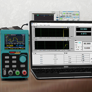
Image: Close-up of the front 5V 1A USB port being used to charge a smartphone.
9.2 Rear Device USB Port (PC Control)
The rear USB port allows connection to a PC for advanced control, data logging, and firmware updates. Download the necessary software from https://bit.ly/37Bwt92. The software enables graphical display of data, remote parameter setting, and waveform programming.
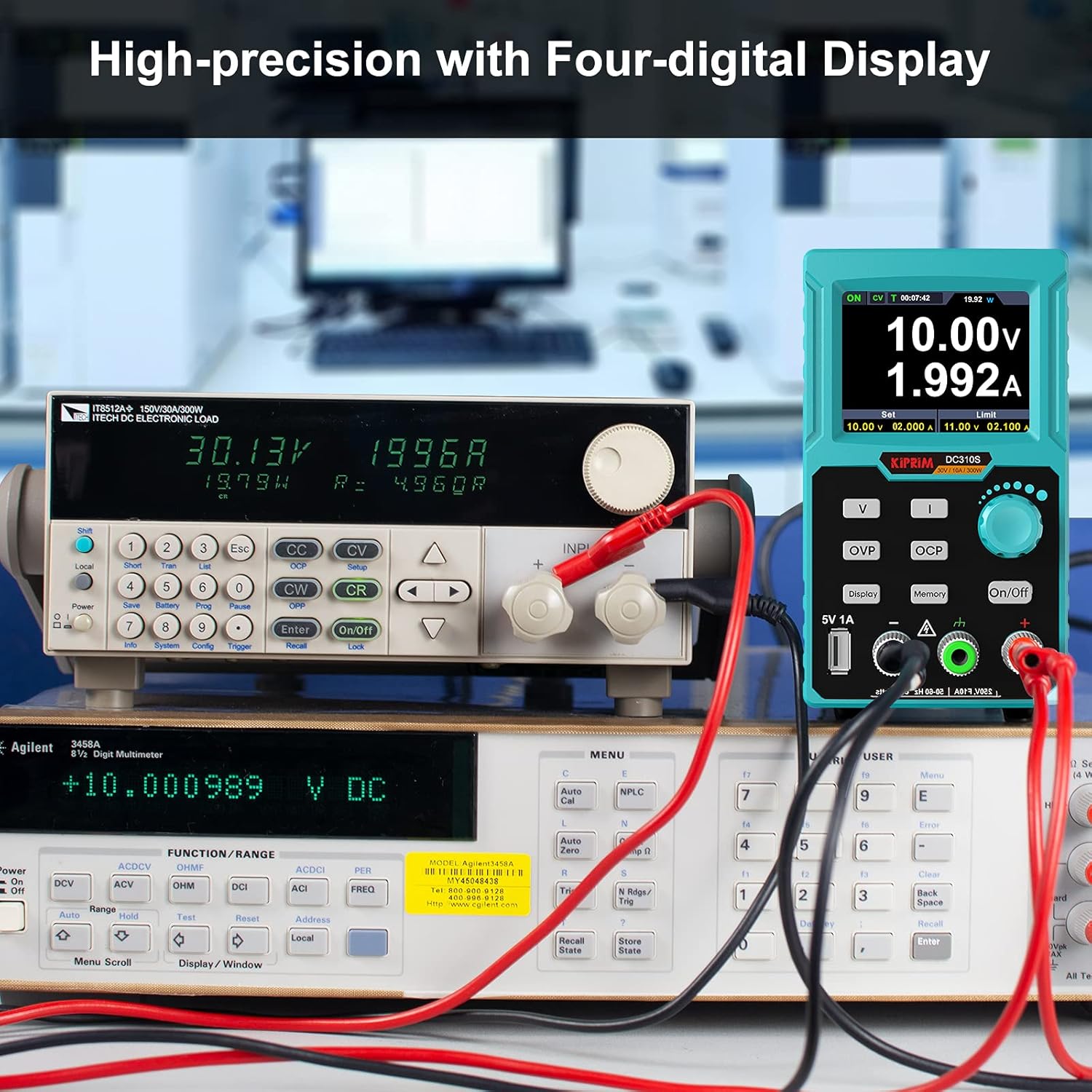
Image: The Kiprim DC310S power supply connected to a laptop, demonstrating PC control and data visualization via software.
10. Maintenance
- Cleaning: Use a soft, dry cloth to clean the exterior of the device. Do not use abrasive cleaners or solvents.
- Ventilation: Regularly check that the cooling fan and ventilation openings are free from dust and debris. Clean as necessary to ensure proper airflow.
- Fuse Replacement: If the device fails to power on, check the fuse in the fuse box on the rear panel. Replace with a fuse of the same type and rating (e.g., F10A 250V).
- Storage: When not in use for extended periods, store the power supply in a cool, dry place, away from direct sunlight and extreme temperatures.
11. Troubleshooting
| Problem | Possible Cause | Solution |
|---|---|---|
| Device does not power on. | No power from outlet; Power cable loose; Blown fuse. | Check power outlet; Secure power cable; Replace fuse. |
| No output voltage/current. | Output is OFF; OVP/OCP triggered; Load disconnected or faulty. | Press 'On/Off' button; Check OVP/OCP settings and reset if necessary; Verify load connection. |
| Display shows error message. | Internal fault; Over-temperature. | Turn off and restart the device. Ensure proper ventilation. If error persists, contact support. |
| Fan is noisy. | High load causing increased heat; Dust in fan. | This is normal under high load. Ensure ventilation is clear. Clean fan if necessary. |
12. Specifications
| Parameter | Value |
|---|---|
| Brand | Kiprim |
| Model Number | DC310S |
| Output Voltage Range | 0-30V |
| Output Current Range | 0-10A |
| Output Power | 300 W |
| Set/Readback Voltage Resolution | 10mV |
| Set/Readback Current Resolution | 1mA |
| Set/Readback Voltage Accuracy | ≤0.1%±20mV |
| Set/Readback Current Accuracy | ≤0.1%±10mA |
| Over-Voltage Protection (OVP) | 0-31V (settable) |
| Over-Current Protection (OCP) | 0-10.1A (settable) |
| Over-Temperature Protection (OTP) | 85°C |
| Display | 2.8-inch Color LCD |
| USB Charging Port | Front 5V 1A (Type-C, Micro USB compatible) |
| PC Connection | Rear USB Port |
| Minimum Input Voltage | 100V AC |
| Product Dimensions (LxWxH) | 22.6 x 8.2 x 14.2 cm |
| Number of Fans | 1 |
| UPC | 782942415530 |
| ASIN | B0928LX2D1 |
13. Warranty and Support
The Kiprim DC310S Programmable DC Power Supply comes with a 12-month warranty from the date of purchase.
For any questions, technical assistance, or warranty claims, please contact Kiprim customer support via email. Please refer to your purchase documentation for specific contact details or visit the official Kiprim website.
