
1. Introduction
This manual provides essential information for the safe and efficient installation, operation, and maintenance of your Silscvtt 24-36V 500W Brushless Motor Speed Square Wave Controller. Please read this manual thoroughly before using the product to ensure proper function and to prevent damage or injury.
2. Important Safety Instructions
- Always disconnect power from the battery before performing any installation, maintenance, or wiring adjustments.
- Installation should ideally be performed by a qualified technician to ensure correct wiring and prevent damage to the controller or motor.
- Ensure all connections are secure and properly insulated to prevent short circuits.
- Do not expose the controller to water, excessive moisture, or extreme temperatures.
- Verify that the battery voltage and motor power rating are compatible with the controller's specifications.
- Keep children and pets away from electrical components during operation and installation.
3. Product Overview
The Silscvtt Brushless Motor Speed Square Wave Controller is designed to provide stable speed control and sensitive response for electric bicycles and scooters. It features an aluminum alloy shell for efficient heat dissipation and supports both sine wave and square wave motors, including those without Hall sensors.
Key Features:
- Provides steady speed and sensitive control for braking and direction changes.
- Offers stronger power output with reduced motor operating noise.
- Compatible with sine wave, square wave, and no-Hall sensor motors.
- Ensures smoother motor startup for a more comfortable ride.
- Constructed with premium materials for effective heat dissipation, preventing thermal overload and internal circuit damage.
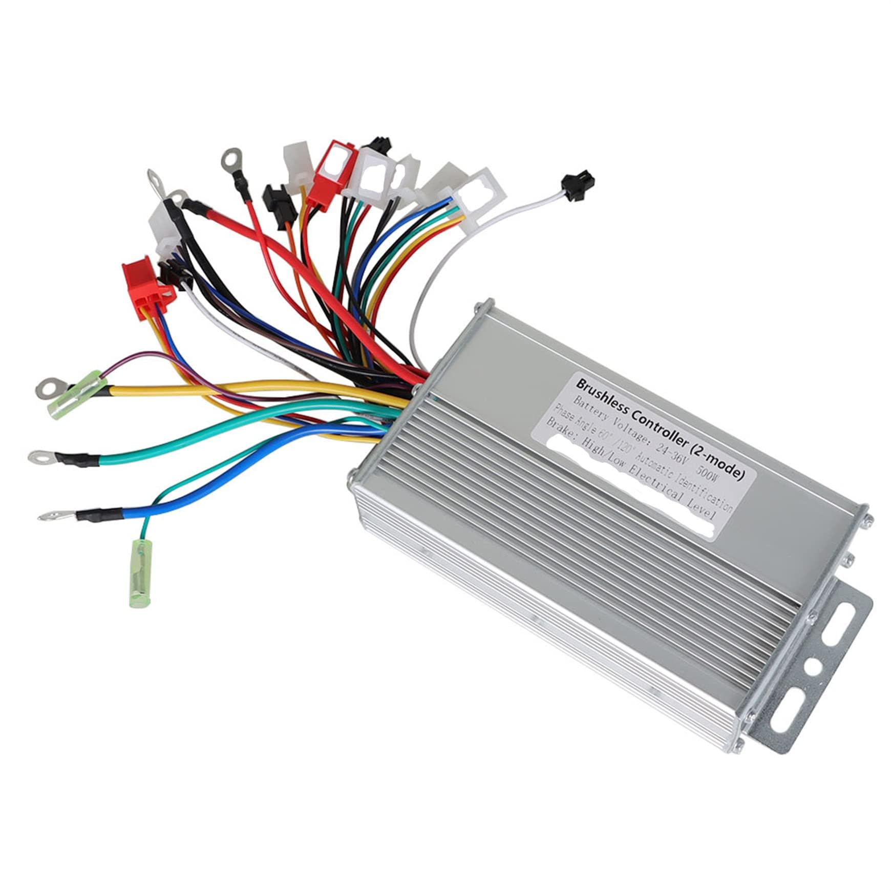
Figure 1: Silscvtt 24-36V 500W Brushless Motor Speed Controller. This image shows the main unit, a silver finned aluminum casing, with a bundle of multi-colored wires and various connectors extending from one end.
4. Technical Specifications
| Specification | Value |
|---|---|
| Battery Voltage | 24-36V |
| Power Output | 500W |
| Brake Type | High/Low Electrical Level |
| Phase Angle | 60° / 120° Automatic Identification |
| Compatibility | Electric bicycles, scooters |
| Dimensions | 7.48 x 4.72 x 1.97 inches (approx.) |
| Weight | 1.08 pounds (approx.) |
5. Setup and Installation
Before beginning installation, ensure the battery is disconnected. Identify each wire bundle from the controller and match them to the corresponding components on your electric bicycle or scooter. Refer to the image below for common connector types.

Figure 2: Controller and various connector types. This image displays the main controller unit at the top, and below it, a grid of nine different electrical connectors, illustrating the variety of interfaces available.
Wiring Connections (Typical):
- Power Wires (Thick Red/Black): Connect the thick red wire to the battery's positive (+) terminal and the thick black wire to the battery's negative (-) terminal. Ensure polarity is correct.
- Motor Phase Wires (Thick Yellow, Green, Blue): Connect these to the corresponding phase wires of your brushless motor.
- Motor Hall Sensor Wires (Thin Red, Black, Yellow, Green, Blue - 5-pin connector): If your motor has Hall sensors, connect these. If your motor is sensorless, these may not be used.
- Throttle Wires (Red, Green, Black - 3-pin connector): Connect to your throttle unit. Red is typically +5V, Green is signal, Black is ground.
- Brake Lever Wires (Often 2-pin connectors, various colors): Connect to your brake levers. These typically cut power to the motor when brakes are applied.
- Power Lock/Ignition (Often 2-pin, Red/Blue): Connect to your ignition switch. This turns the controller on/off.
- Self-Learning Wires (Often 2 white wires): These are used for automatic phase angle identification. Connect them together briefly, turn on power, and the motor will spin. If it spins correctly, disconnect them. If it spins backward, disconnect, reconnect, and it should reverse. Once correct, disconnect and do not reconnect during normal operation.
- Indicator/Display Wires (Various, e.g., Headlight, Power Display): Connect these to your dashboard or lights as appropriate.
After all connections are made, double-check them for security and correct polarity before reconnecting the battery. Secure the controller in a location that is protected from physical damage and allows for adequate airflow for cooling.
6. Operating Instructions
- Power On: Turn the ignition key or power switch to the 'ON' position. The system should power up.
- Throttle Control: Gently twist the throttle grip to accelerate. The motor speed will increase proportionally to the throttle input.
- Braking: Apply the brake levers. The controller will cut power to the motor, allowing the brakes to function effectively.
- Power Off: Turn the ignition key or power switch to the 'OFF' position when you are finished riding.
7. Maintenance
- Regular Inspection: Periodically check all wiring connections for tightness and signs of wear or corrosion.
- Cleaning: Keep the controller clean and free from dust, dirt, and debris. Use a dry, soft cloth for cleaning. Do not use water or solvents.
- Heat Dissipation: Ensure the controller's fins are not obstructed to allow for proper heat dissipation.
- Avoid Impact: Protect the controller from physical impacts or drops.
8. Troubleshooting
| Problem | Possible Cause | Solution |
|---|---|---|
| Motor does not spin | No power to controller; Loose connections; Faulty throttle; Brake engaged. | Check battery connection and charge; Verify all wiring; Test throttle; Ensure brake levers are not engaged. |
| Motor spins intermittently | Loose motor phase wires or Hall sensor wires; Intermittent throttle signal. | Inspect and secure all motor and Hall sensor connections; Check throttle wiring. |
| Motor runs but with reduced power | Low battery voltage; Incorrect phase angle setting; Overheating. | Charge battery; Re-run self-learning procedure; Allow controller to cool down. |
| Controller gets excessively hot | Overload; Insufficient ventilation; Short circuit. | Reduce load; Ensure proper airflow around controller; Check for short circuits in wiring. |
9. Warranty and Support
This product is covered by a limited warranty against manufacturing defects. For specific warranty terms and conditions, please refer to the product packaging or contact the retailer from whom you purchased the item. For technical support or further assistance, please contact Silscvtt customer service through their official channels or the retailer.