Introduction
This user manual provides detailed instructions for the installation, operation, and maintenance of the FusyTuly R01-180KG Magnetic Lock Access Control System Kit. This wireless system offers convenient and secure access management for various door types, including metal, wood, glass, and sliding doors. It supports remote control and exit button unlocking methods, operating on a 433 MHz frequency.
Package Contents
Please verify that all components listed below are included in your package:
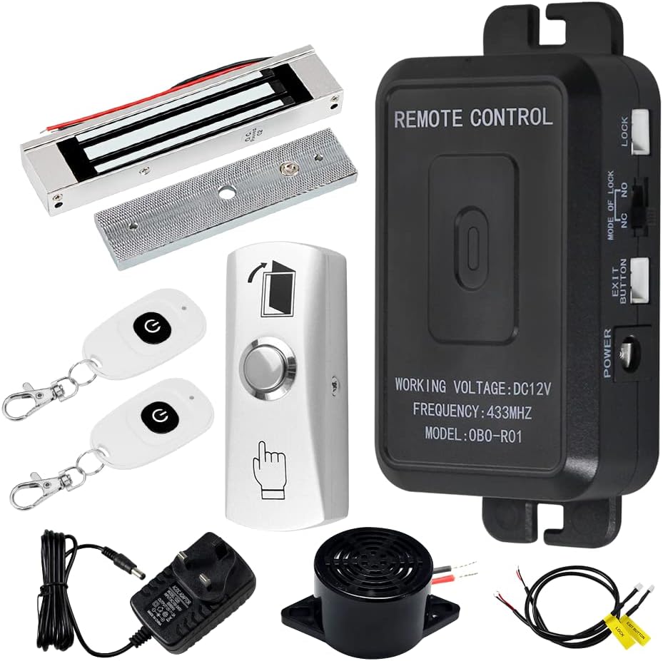
This image displays all the components included in the FusyTuly R01-180KG Magnetic Lock Access Control System Kit. From top left, clockwise: a magnetic lock with its armature plate, a black remote control receiver unit, an exit button, two white remote keyfobs, a power adapter, and a small speaker/buzzer.
- 1 x Magnetic Lock (180KG/350lbs holding force)
- 1 x Remote Control Receiver Unit (Model: 0B0-R01)
- 2 x Remote Keyfobs (433MHz)
- 1 x Exit Button
- 1 x Power Adapter (DC12V output)
- 1 x Speaker/Buzzer
- Necessary wiring and mounting hardware
Specifications
| Component | Specification |
|---|---|
| Magnetic Lock |
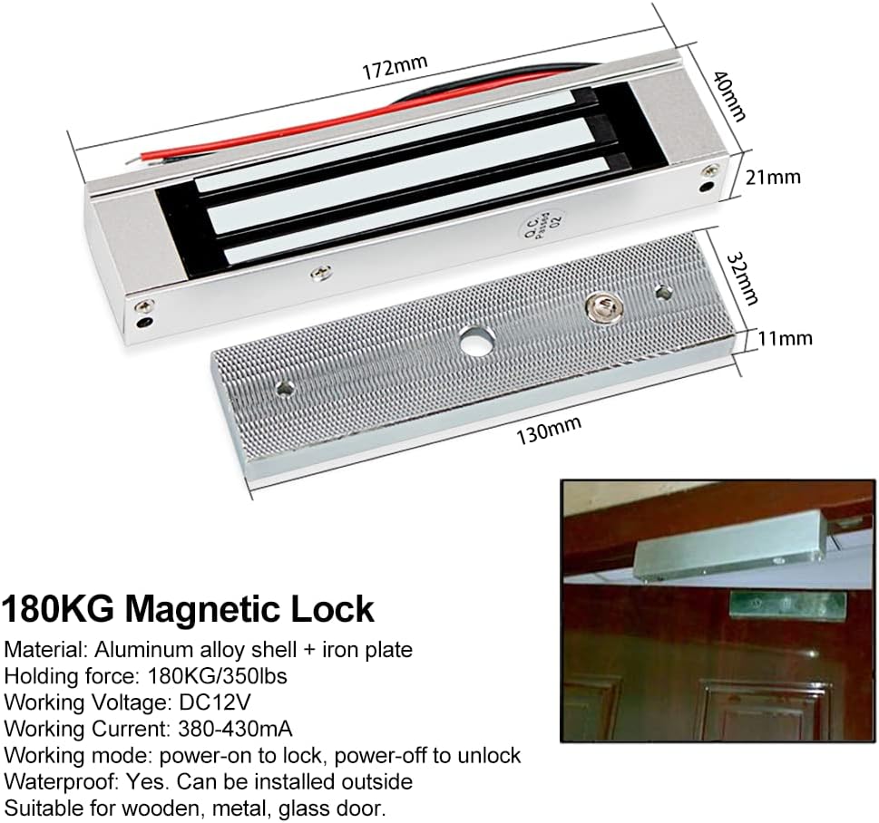 This image illustrates the dimensions of the 180KG magnetic lock and its corresponding armature plate, showing length, width, and height measurements. |
| Remote Control Receiver Unit |
 This image shows the dimensions of the black remote control receiver unit, including its length, width, and height. |
| Remote Keyfob |
|
| Door Exit Button |
|
Safety Information
- Ensure power is disconnected before performing any wiring or installation.
- Only use the provided power adapter or a compatible DC12V power source.
- Do not expose the components to extreme temperatures or humidity beyond specified ranges.
- Consult a qualified electrician if you are unsure about any wiring procedures.
- Keep remote keyfobs out of reach of children to prevent unintended access.
Setup and Installation
1. Component Identification

This image shows the internal circuit board of the remote control receiver unit with key components labeled, including RF-KEY, Operating Mode switch, Access Controller, Speaker, Lock terminals (NC, NO), Exit Button terminals, and Power Supply input.
Familiarize yourself with the main control board of the remote control receiver unit. The image above highlights important connection points and switches.
2. Wiring Diagram

This diagram illustrates the wiring connections between the main control board, power supply, exit button, and magnetic lock. Note the connection for the magnetic lock should be switched to "NC" (Normally Closed) for fail-safe operation.
Follow the wiring diagram carefully. Ensure all connections are secure and correctly polarized. The magnetic lock should be connected to the "NC" (Normally Closed) terminals for fail-safe operation, meaning the door will unlock in case of power failure.
- Connect the Power Adapter to the DC12V input on the Remote Control Receiver Unit.
- Connect the Exit Button to the "Exit Button" terminals on the receiver unit.
- Connect the Magnetic Lock to the "NC" (Normally Closed) and "COM" terminals on the receiver unit.
- Connect the Speaker/Buzzer to its designated terminals on the receiver unit (if applicable).
3. Lock Mode Selection and Time Delay Adjustment

This image highlights the switches on the remote control receiver unit for selecting the lock mode (NO/NC) and adjusting the time delay (0, 5, or 10 seconds). It also indicates the RF-KEY button for remote control pairing.
- Lock Mode Select: Use the switch labeled "MODE OF LOCK" to select between NO (Normally Open) and NC (Normally Closed). For the magnetic lock provided, select NC (Fail-Safe Lock).
- Time Delay: Adjust the switch labeled "TIME" to set the unlock delay to 0, 5, or 10 seconds. 5 seconds is the default setting. This determines how long the door remains unlocked after activation.
4. Remote Control Transmitter Pairing
To pair a remote keyfob with the receiver unit:
- Ensure the receiver unit is powered on.
- Press the "RF-KEY" button on the receiver unit (refer to Component Identification image for location). The indicator light will illuminate.
- While the indicator light is on, press any button on the remote keyfob you wish to pair.
- The indicator light on the receiver unit will flash and then turn off, indicating successful pairing.
- Repeat for any additional remote keyfobs.
Operating Instructions
The FusyTuly access control system supports two primary methods for unlocking the door:

This image visually demonstrates the two primary methods for unlocking the door: using the remote control keyfob and pressing the physical exit button.
1. Remote Control Unlock
Press the unlock button on the paired remote keyfob. The door will unlock for the duration set by the time delay switch (0, 5, or 10 seconds). The remote control has an effective range of up to 30 meters.
2. Exit Button Unlock
From inside, press the physical exit button installed near the door. This will momentarily unlock the door, allowing egress. The door will re-lock automatically after the set time delay.

This diagram provides an overview of the complete access control system, showing the connections between the remote control receiver, magnetic lock, exit button, power supply, and illustrating the use of the remote keyfob.
Maintenance
- Cleaning: Wipe components with a soft, dry cloth. Avoid abrasive cleaners or solvents.
- Magnetic Lock: Ensure the magnetic lock and armature plate are clean and free of debris to maintain optimal holding force. Periodically check for proper alignment.
- Wiring: Periodically inspect all wiring connections for signs of wear, corrosion, or looseness. Re-secure any loose connections.
- Remote Keyfobs: If the remote control range decreases significantly, consider replacing the CR2016 batteries (2x per keyfob).
- Environmental Conditions: While the magnetic lock is waterproof, protect the receiver unit and power adapter from direct exposure to water or extreme weather conditions.
Troubleshooting
| Problem | Solution |
|---|---|
| Door does not lock/unlock. |
|
| Remote control range is poor. |
|
| Door unlocks immediately or stays unlocked too long. |
|
| Magnetic lock is not holding securely. |
|
Warranty and Support
For warranty information or technical support, please refer to the product listing page on Amazon or contact FusyTuly customer service directly. Keep your purchase receipt as proof of purchase.


