1. Introduction
This manual provides essential information for the safe and efficient operation of your Volt Polska Sinus PRO ULTRA 4000 Solar Inverter. This device integrates an inverter, a solar charger, and a battery charger into a single unit, designed to provide reliable power for various applications. Please read this manual thoroughly before installation and use, and retain it for future reference.
2. Safety Instructions
WARNING: Failure to follow these instructions may result in serious injury, death, or damage to the inverter and other property.
- Installation must be performed by qualified personnel.
- Ensure all wiring is correctly sized and properly connected.
- Do not open the inverter casing. There are no user-serviceable parts inside.
- Keep the device away from water, moisture, and flammable materials.
- Ensure adequate ventilation around the inverter to prevent overheating.
- Disconnect all power sources (AC, DC, PV) before performing any maintenance or wiring.
- This inverter produces high voltage. Exercise extreme caution.
3. Product Overview
The Sinus PRO ULTRA 4000 is a versatile solar inverter designed for optimal energy management. It features a clear LCD display for monitoring and configuration.
3.1 Front Panel

Figure 3.1: Front View of the Inverter. This image displays the front panel of the Volt Polska Sinus PRO ULTRA 4000 solar inverter, featuring the LCD screen, control buttons, and the Volt Polska logo. A caution label is visible on the lower left, and product specifications are printed on the lower right.
The front panel includes the LCD display and control buttons for navigating menus and adjusting settings. Indicators for AC input, inverter status, charging, and fault conditions are also present.
3.2 Side and Rear Panels
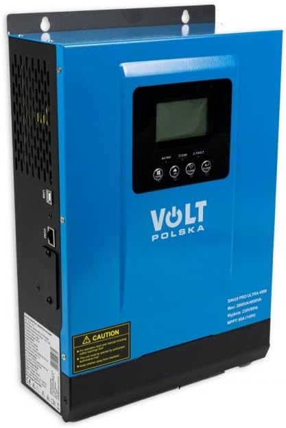
Figure 3.2: Angled View. This image shows the Volt Polska Sinus PRO ULTRA 4000 solar inverter from an angled perspective, highlighting the side ventilation grilles and the overall compact design. The front panel with its display and controls is also visible.
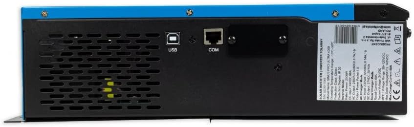
Figure 3.3: Rear Communication Ports. This image focuses on the rear section of the inverter, displaying the USB and COM (RJ45) communication ports, along with ventilation openings. This allows for connection to a computer for monitoring and software updates.

Figure 3.4: Side Power Switch. This image shows the side of the inverter, featuring the main ON/OFF power switch and a caution label with important operational notes. Ventilation grilles are also visible.

Figure 3.5: Wiring Terminals. This image displays the bottom panel of the inverter, showing the terminals for AC input, AC output, DC battery input (DC+ and DC-), and PV solar panel input (PV+ and PV-). An input breaker is also visible.
The side panels feature ventilation grilles for heat dissipation. The rear panel houses communication ports (USB, COM) for connecting to a computer. The bottom panel contains the main wiring terminals for AC input, AC output, DC battery connections, and PV solar panel connections, along with the main ON/OFF switch and an input breaker.
3.3 Included Accessories

Figure 3.6: Accessories. This image shows the accessories included with the inverter: a USB communication cable, a metal mounting bracket, and two screws for installation.
The package typically includes a USB cable for PC connection, a mounting bracket, and screws for installation.
4. Setup and Installation
Proper installation is critical for the safe and efficient operation of the inverter. Refer to Figure 3.5 for terminal locations.
- Mounting: Choose a suitable location that is dry, well-ventilated, and away from direct sunlight. Use the provided mounting bracket and screws to securely attach the inverter to a wall.
- Battery Connection: Connect the battery bank to the DC+ and DC- terminals. Ensure correct polarity. Use appropriate cable gauges for the current draw.
- PV Array Connection: Connect the solar panel array to the PV+ and PV- terminals. Verify that the PV input voltage is within the specified range (30VDC-130VDC).
- AC Input Connection: Connect the AC utility grid to the AC INPUT terminals.
- AC Output Connection: Connect your loads to the AC OUTPUT terminals.
- Grounding: Ensure the inverter is properly grounded according to local electrical codes.
- Initial Power-Up: After all connections are secure, switch on the DC breaker (if present), then the AC input breaker (if present), and finally the main ON/OFF switch on the inverter (Figure 3.4).
5. Operating Instructions
The inverter features an LCD display and control buttons for configuration. The display provides real-time information on system status, battery voltage, PV input, AC output, and more.
5.1 LCD Display and Buttons
Use the buttons below the LCD to navigate through menus and adjust settings. Common settings include:
- Battery Charging Current: Configurable based on battery type and capacity.
- AC/Solar Charger Priority: Set whether the inverter prioritizes AC utility power or solar power for charging.
- Input Voltage Range: Adjust for household appliances or sensitive electronics.
Refer to the on-screen menu for detailed parameter adjustments. A PC software link is mentioned in the product description for advanced monitoring and control.
Note: For PC software download, please refer to the product's official support page or the link provided in the original product description.
5.2 Pure Sine Wave Output
The inverter produces a pure sine wave output, identical to the utility grid. This makes it suitable for powering sensitive electronics and inductive loads such as refrigerators, motors, and power tools without risk of damage.
6. Maintenance
Regular maintenance ensures the longevity and optimal performance of your inverter.
- Cleaning: Keep the inverter clean and free from dust. Use a dry cloth to wipe the exterior. Do not use liquid cleaners.
- Ventilation: Ensure that the ventilation openings are not blocked. Periodically check for dust accumulation in the vents and clean if necessary.
- Connections: Periodically check all electrical connections for tightness and signs of corrosion.
- Battery Health: Monitor battery voltage and health as recommended by the battery manufacturer.
7. Troubleshooting
This section addresses common issues you might encounter. For problems not listed here, contact customer support.
| Problem | Possible Cause | Solution |
|---|---|---|
| Inverter not turning on | No battery connection, low battery voltage, main switch off. | Check battery connections, charge battery, turn on main switch. |
| No AC output | Overload, short circuit, fault condition, battery low. | Reduce load, check for short circuits, check fault codes on LCD, charge battery. |
| Battery not charging from PV | PV voltage too low/high, PV connections incorrect, solar panels shaded. | Check PV voltage, verify connections, clear shading. |
| Overheating warning | Blocked ventilation, excessive ambient temperature, overload. | Ensure clear ventilation, move to cooler location, reduce load. |
8. Specifications
Technical specifications for the Volt Polska Sinus PRO ULTRA 4000 (Model: 3SSH200024).
- Total Power (Instantaneous): 4000 VA
- Constant Power: 2000 W
- Battery Voltage: 24 VDC
- PV Input Voltage Range: 30VDC - 130VDC
- Max Charge Current (MPPT): 60A
- AC Input Voltage Range: 170VAC - 280VAC
- AC Output Voltage Range (Utility): 220VAC - 240VAC
- Grid Charge Current: 20/30A
- Inverter Output Voltage: 230V ±3%
- Operating Temperature: 0-40°C
- Dimensions: 224 x 337 x 97 mm
- Weight: 5.7 kg
9. Warranty and Support
For warranty information, technical support, or service inquiries, please contact your retailer or the manufacturer, Volt Polska. Keep your purchase receipt as proof of purchase.
Note: Information regarding spare parts availability and software updates is not explicitly provided in the product details. Please consult the manufacturer's official website or contact their support for the most current information.


