1. Introduction
This manual provides detailed instructions for the proper use, setup, operation, and maintenance of the AAI N1201SA+ RF Vector Impedance Antenna Analyzer. This device is designed for accurate measurement and analysis of RF parameters, including impedance, VSWR, and S11, across a frequency range of 35MHz to 2.7GHz.
2. Safety Information
- Do not expose the device to extreme temperatures, moisture, or direct sunlight.
- Avoid dropping or subjecting the device to severe impacts.
- Use only the specified charging cable and power adapter to prevent damage.
- Do not attempt to open or repair the device yourself. Refer to qualified service personnel.
- Ensure proper ventilation during operation.
3. Product Overview
3.1 Key Features
- Wide Frequency Range: Operates from 35MHz to 2700MHz.
- High Resolution: Frequency step of 1kHz for precise tuning.
- Detailed Measurements: Provides R (Resistance), X (Reactance), VSWR (Voltage Standing Wave Ratio), and S11 (Return Loss) values.
- Portable Design: Equipped with a 2000mAH (7.4Wh) battery for field use.
- UV Band Capability: Unique capability for UV band analysis.
- High Impedance Resolution: Minimum impedance resolution of 0.001.
3.2 Device Components

Figure 1: Front view of the AAI N1201SA+ RF Vector Impedance Antenna Analyzer. The device features a color display showing measurement parameters, along with control buttons for navigation and operation.
- Display Screen: Shows frequency, R, X, VSWR, S11, and other measurement data.
- M Button: Menu/Mode selection.
- Left/Right Arrow Buttons: Navigation and parameter adjustment.
- OK Button: Confirm selection or action.
- CTRL Button: Control function, often used in combination with other buttons.
- Power Button: Turns the device on/off.
- RF Connector: For connecting antennas or test loads (typically SMA female).
- Charging Port (Micro USB): For battery charging.
- Reset Button: For device reset.

Figure 2: Top view of the AAI N1201SA+ showing the RF connector, labeled for 10dBm RF 0VDC Max input.
4. Setup
4.1 Initial Charging
Before first use, fully charge the device battery. Connect the provided Micro USB cable to the charging port on the side of the analyzer and plug it into a suitable USB power source.
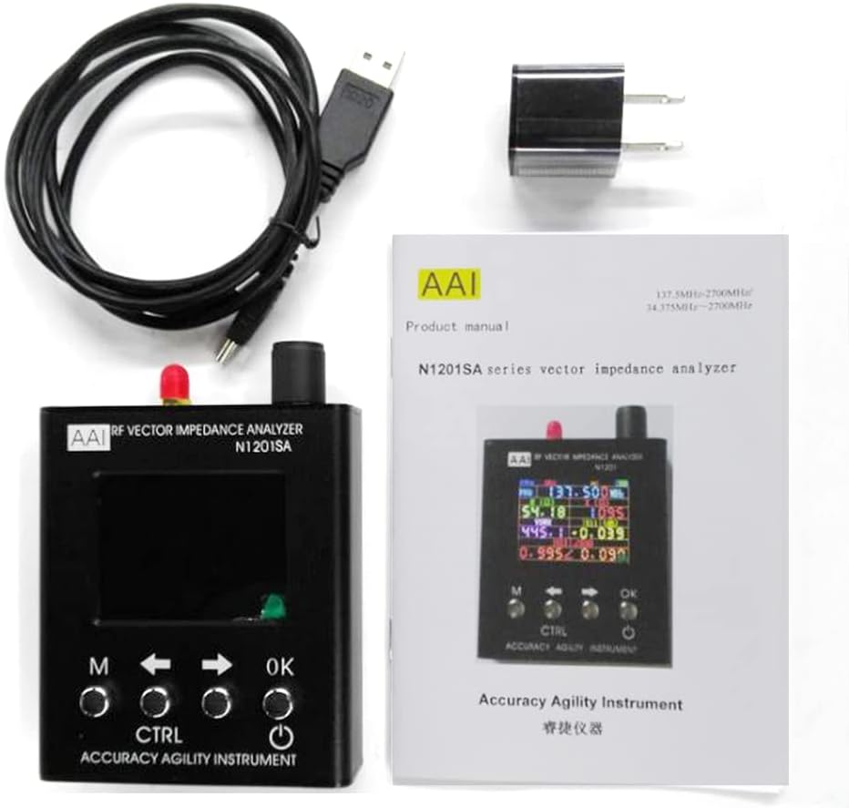
Figure 3: Side view of the AAI N1201SA+ illustrating the charging port and Micro USB port.
4.2 Preheating for Accuracy
To ensure the accuracy of measurements and calibration, it is recommended to preheat the instrument for at least 15 minutes before performing critical tests.
4.3 Connecting an Antenna or Load
Carefully connect the antenna or test load to the RF connector on the top of the analyzer. Ensure the connection is secure to avoid inaccurate readings.
5. Operating Instructions
5.1 Power On/Off
- Power On: Press the Power button (usually located on the right side).
- Power Off: From the boot state, long-press (for 2 seconds or more) the Power button, then release. The instrument will shut down.
- Forced Shutdown: In a shutdown state, hold down the CTRL key and then press the Power button to initiate a forced shutdown.
5.2 Basic Measurement Mode
Upon powering on, the device typically defaults to a measurement display showing various parameters. Use the arrow keys to navigate or adjust frequency.

Figure 4: Display showing numerical values for frequency, R, X, VSWR, and S11.
5.3 Graph Mode
The analyzer can display measurement data graphically, which is useful for visualizing frequency sweeps and performance trends.

Figure 5: Display showing a graphical representation of measurement data, indicating start and stop frequencies.
5.4 Adjusting Frequency
Use the Left and Right arrow buttons to adjust the operating frequency. The frequency step is 1kHz, allowing for fine-tuning.
5.5 Menu Navigation
Press the 'M' button to access the main menu. Use the arrow keys to scroll through options and 'OK' to select. Refer to the on-screen prompts for specific menu functions such as calibration, sweep settings, or saving data.
6. Maintenance
- Cleaning: Use a soft, dry cloth to clean the device. Do not use abrasive cleaners or solvents.
- Storage: Store the analyzer in a cool, dry place away from direct sunlight and extreme temperatures.
- Battery Care: For long-term storage, ensure the battery is partially charged (around 50%) to prolong its lifespan. Recharge periodically if stored for extended periods.
7. Troubleshooting
- Device not powering on: Ensure the battery is charged. If not, connect to a charger. If still unresponsive, try the forced shutdown/restart procedure (hold CTRL + Power).
- Inaccurate readings: Ensure the device has preheated for at least 15 minutes. Check all cable connections for tightness. Perform a calibration if available in the menu.
- Display frozen: Try restarting the device using the power off procedure. If unresponsive, use the Reset button (if accessible, often a small pinhole).
- Battery not charging: Verify the charging cable and adapter are working correctly. Try a different USB power source.
8. Specifications
| Parameter | Value |
|---|---|
| Working Frequency | 35MHz ~ 2700MHz |
| Frequency Step | 1kHz |
| Battery Capacity | 2000mAH (7.4Wh) |
| Impedance Resolution | 0.001 (minimum) |
| Color | Black |
| Manufacturer | YZTERA |
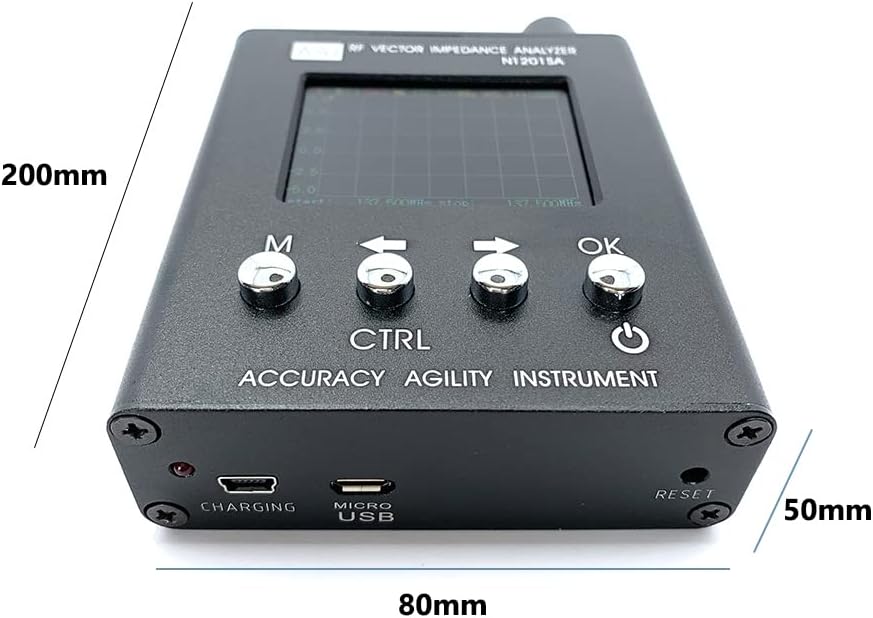
Figure 6: Approximate dimensions of the AAI N1201SA+ analyzer.
9. Warranty and Support
For warranty information, technical support, or service inquiries, please refer to the documentation provided with your purchase or contact the retailer. Keep your proof of purchase for warranty claims.


