1. Product Overview
The ALLmeter BM4070 is a digital LCR meter designed for precise measurement of capacitance, inductance, and resistance. This instrument features a wide measuring range, high accuracy, and a fast sampling rate, making it suitable for various electrical testing applications. Its user-friendly design includes an easy-to-read LCD display, data hold function, and automatic power-off for convenience.

Figure 1: ALLmeter BM4070 LCR Meter highlighting its core measurement functions.
Key Features:
- Wide Measuring Range: Measures capacitance from 200 pF to 2000 uF, inductance from 200 uH to 20 H, and resistance from 200 Ω to 20 MΩ.
- High Accuracy: Provides precise readings with an accuracy of approximately ±(reading + digits)%.
- Fast Sampling Rate: Offers real-time and accurate measurements with a sampling rate of 3 times per second.
- Easy-to-Read Display: Features an LCD display capable of showing up to 1999 (3 1/2) digits, ensuring clear visibility even in low-light conditions.
- Multiple Measurement Modes: Capable of measuring inductance, capacitance, resistance, and the forward voltage drop of diodes.
- Convenient Functions: Includes auto power-off, data hold, and overrange display.
- Portable Design: Compact and comes with a portable bag for easy storage and transport.
What's in the Box:
- 1 x ALLmeter BM4070 LCR Meter
- 1 x Pair of Crocodile Clips
- 1 x 9V Battery
- 1 x User Manual
- 1 x Portable Bag
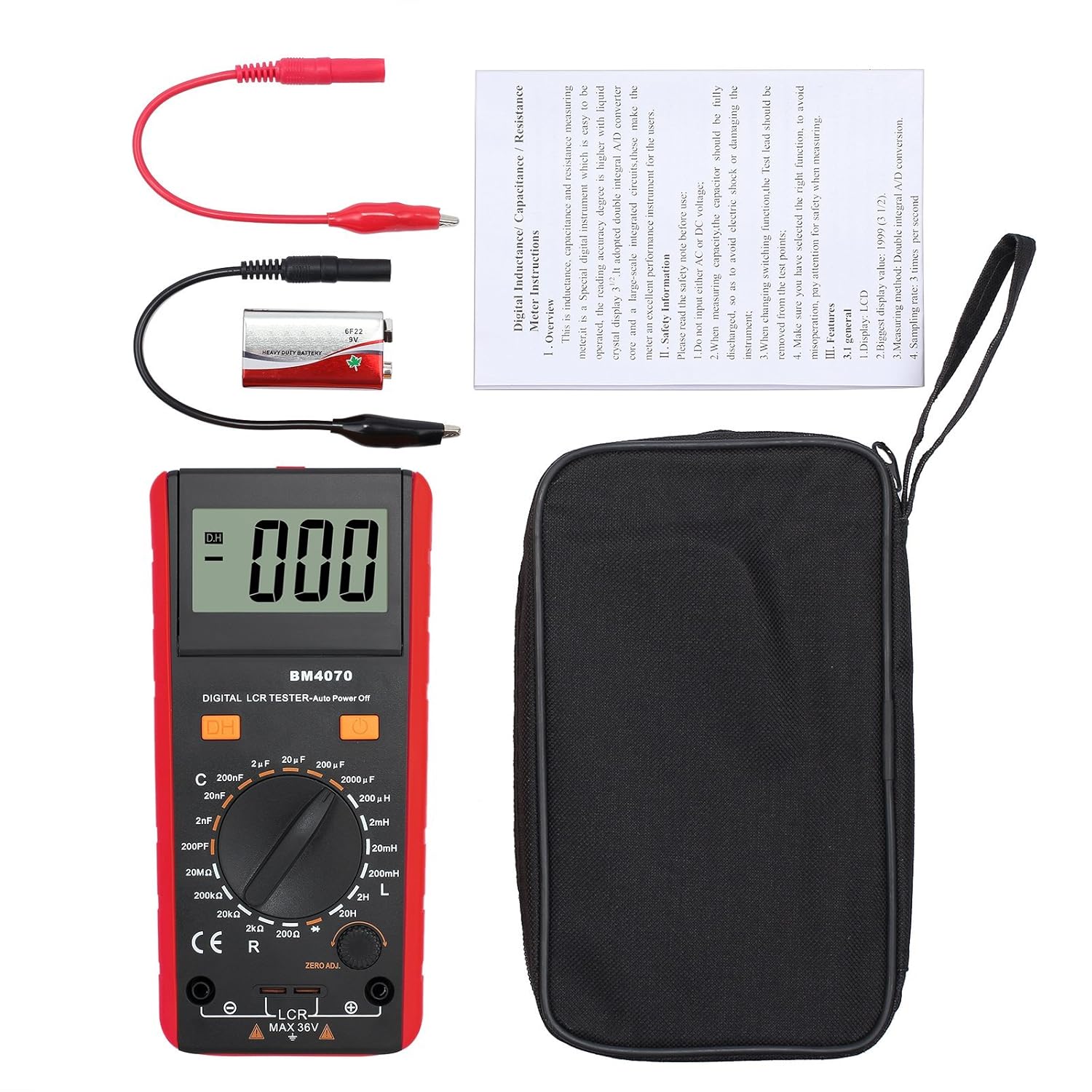
Figure 2: Package contents of the BM4070 LCR Meter.
2. Safety Information
To ensure safe operation and prevent damage to the instrument, please read and adhere to the following safety guidelines:
- Voltage Input: Do not apply external voltage to the input terminals, as this can damage the instrument.
- Capacitor Discharge: Before measuring capacitance, always ensure that the capacitor is fully discharged. Failure to do so can result in electric shock or damage to the meter.
- Function Switching: When changing measurement functions, always remove the test leads from the test points to prevent incorrect readings or potential hazards.
- Maximum Input: Do not exceed the maximum input voltage of 36V DC/AC RMS for the LCR terminals.
- Battery Safety: Ensure the 9V battery is correctly installed. Replace the battery when the low power indicator appears on the display.
- Environmental Conditions: Operate the meter within the specified temperature and humidity ranges. Avoid using it in environments with excessive dust, moisture, or corrosive gases.
- Maintenance: Refer to the maintenance section for proper cleaning and battery replacement procedures. Do not attempt to modify or repair the instrument yourself.
3. Product Components
Familiarize yourself with the different parts of your BM4070 LCR Meter:
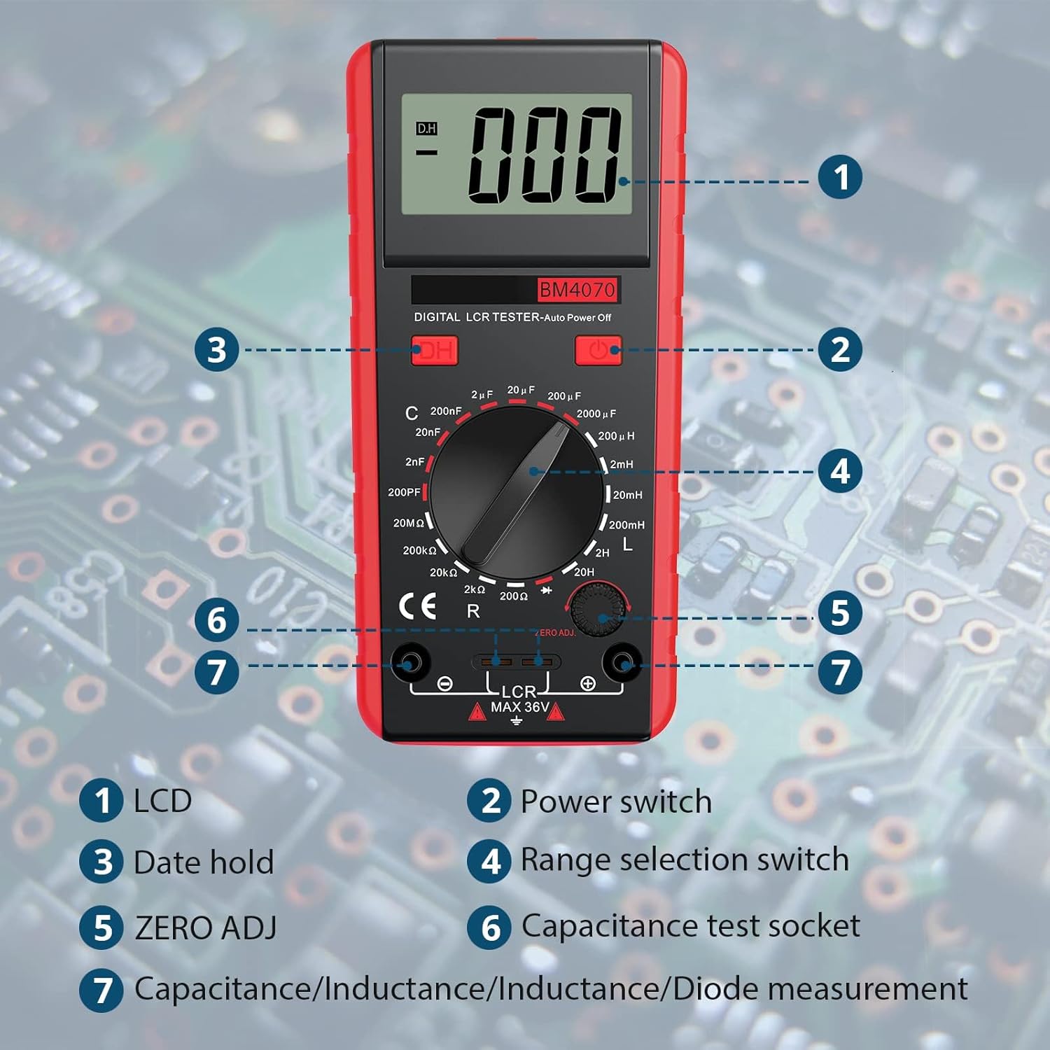
Figure 3: Labeled components of the BM4070 LCR Meter.
- LCD Display: Shows measurement readings, units, and function indicators.
- Power Switch: Turns the device ON or OFF.
- Data Hold (DH) Button: Freezes the current reading on the display.
- Range Selection Switch: Rotary switch to select the desired measurement function (C, L, R, Diode) and range.
- ZERO ADJ Knob: Used to zero out residual capacitance or inductance before measurement, especially for small values.
- Capacitance Test Socket: Dedicated socket for direct insertion of small capacitors for measurement.
- Measurement Terminals (LCR MAX 36V): Input jacks for connecting crocodile clips or test leads for measuring L, C, R, and Diode.
4. Setup
4.1 Battery Installation
The BM4070 LCR Meter requires one 9V battery for operation. A battery is included in the package.
- Locate the battery compartment cover on the back of the meter.
- Use a screwdriver or coin to open the battery cover.
- Connect the 9V battery to the battery clip, ensuring correct polarity.
- Place the battery inside the compartment and close the cover securely.
4.2 Connecting Test Leads
The meter comes with a pair of crocodile clips for connecting to components.
- Insert the red plug of the crocodile clip into the red measurement terminal (positive).
- Insert the black plug of the crocodile clip into the black measurement terminal (negative).
- Ensure the connections are secure before proceeding with measurements.
5. Operation
5.1 Powering On/Off
Press the red power switch button to turn the meter ON. Press it again to turn the meter OFF.
5.2 Selecting Measurement Mode and Range
Rotate the central range selection switch to choose the desired measurement function (C for Capacitance, L for Inductance, R for Resistance, or Diode symbol for Diode test) and the appropriate range. Always start with a higher range if the component value is unknown to prevent overrange indication.
5.3 Zero Adjustment (ZERO ADJ)
Before measuring small capacitance or inductance values, it is recommended to perform a zero adjustment to compensate for residual values in the test leads or internal circuitry.
- Ensure the test leads are open (not connected to any component).
- Select the desired capacitance or inductance range.
- Turn the ZERO ADJ knob until the display reads as close to zero as possible.
5.4 Performing Measurements
After selecting the function and range, connect the component to be measured to the crocodile clips or insert small capacitors directly into the capacitance test socket.

Figure 4: Examples of measuring different electronic components.
Capacitance Measurement (C):
- Discharge the capacitor completely before connecting it.
- Select the appropriate capacitance range.
- Connect the capacitor to the test leads or insert into the capacitance test socket.
- Read the capacitance value from the LCD.
Inductance Measurement (L):
- Select the appropriate inductance range.
- Connect the inductor to the test leads.
- Read the inductance value from the LCD.
Resistance Measurement (R):
- Ensure the circuit is de-energized before measuring resistance.
- Select the appropriate resistance range.
- Connect the resistor to the test leads.
- Read the resistance value from the LCD.
Diode Test:
- Select the diode test function.
- Connect the diode to the test leads.
- The display will show the forward voltage drop of the diode. An open circuit (OL) indicates a reverse-biased or faulty diode.
5.5 Data Hold Function
Press the 'DH' button to freeze the current reading on the display. Press it again to release the hold function and resume live measurements.
5.6 Auto Power Off
The meter is equipped with an auto power-off feature to conserve battery life. If no operation is performed for approximately 15 minutes, the meter will automatically shut down. To reactivate, press the power switch.
6. Specifications
Detailed technical specifications for the ALLmeter BM4070 LCR Meter:

Figure 5: Detailed measurement specifications.
6.1 Measurement Ranges and Accuracy:
| Function | Range | Accuracy | Resolution |
|---|---|---|---|
| Capacitance (C) | 200 pF | ±(2.5% + 5) | 0.1 pF |
| 2 nF | 1 pF | ||
| 20 nF | 10 pF | ||
| 200 nF | 100 pF | ||
| 2 µF | 1 nF | ||
| 20 µF | 10 nF | ||
| 2000 µF | 1 µF | ||
| Resistance (R) | 200 Ω | ±(0.8% + 2) | 0.1 Ω |
| 2 kΩ | 1 Ω | ||
| 20 kΩ | 10 Ω | ||
| 20 MΩ | 10 kΩ | ||
| Inductance (L) | 200 µH | ±(3.0% + 5) | 0.1 µH |
| 2 mH | 1 pH | ||
| 20 mH | 10 µH | ||
| 200 mH | 100 µH | ||
| 2 H | 1 mH | ||
| Diode Test | Forward Voltage Drop | Approx. 1mA DC current, 2.8V DC reverse voltage | Display forward voltage approximation |
6.2 General Specifications:
- Display: 1999 counts (3 1/2 digits) LCD
- Sampling Rate: 3 times per second
- Measurement Type: LCR Meter (Double integral A/D converter core)
- Power Source: 1 x 9V Battery (included)
- Item Weight: Approximately 16 ounces (453g)
- Package Dimensions: 8.7 x 5.24 x 2.32 inches (22.1 x 13.3 x 5.9 cm)
- Operating Temperature: 0°C to 50°C (32°F to 122°F)
- Storage Temperature: -10°C to 60°C (14°F to 140°F)
- Overrange Display: "1" at the highest digit
7. Maintenance
Proper maintenance ensures the longevity and accuracy of your BM4070 LCR Meter.
7.1 Cleaning
- Wipe the meter's casing with a soft, damp cloth. Do not use abrasive cleaners or solvents.
- Ensure no moisture enters the meter's casing or terminals.
7.2 Battery Replacement
When the low battery indicator appears on the LCD, replace the 9V battery promptly to ensure accurate measurements.
- Turn off the meter and disconnect all test leads.
- Open the battery compartment cover on the back of the unit.
- Remove the old 9V battery and replace it with a new one, observing correct polarity.
- Securely close the battery compartment cover.
7.3 Storage
- If the meter will not be used for an extended period, remove the battery to prevent leakage.
- Store the meter in its portable bag in a cool, dry place, away from direct sunlight and extreme temperatures.
8. Troubleshooting
If you encounter issues with your BM4070 LCR Meter, refer to the following common problems and solutions:
| Problem | Possible Cause | Solution |
|---|---|---|
| Meter does not power on. | Dead or incorrectly installed battery. | Check battery polarity and replace with a fresh 9V battery. |
| "OL" (Overload) displayed. | Measurement value exceeds the selected range; open circuit. | Select a higher range or check if the component is properly connected and not open. |
| Inaccurate readings. | Low battery; incorrect range selected; residual capacitance/inductance; poor test lead connection. | Replace battery; select appropriate range; perform ZERO ADJ; ensure secure test lead connection. |
| Display is dim or flickering. | Low battery. | Replace the 9V battery. |
9. Warranty and Support
The ALLmeter BM4070 LCR Meter is designed for reliability and performance. For warranty information or technical support, please refer to the contact details provided with your purchase documentation or visit the official ALLmeter website. Keep your purchase receipt as proof of purchase for warranty claims.


