
1. Introduction
Thank you for choosing the ApisQueen 120A Electronic Speed Controller (ESC). This manual provides essential information for the proper installation, operation, and maintenance of your ESC. Designed for RC airplane and drone models, this brushless ESC features a C8051 F850 microcontroller, ensuring stable performance and multiple protection functions. Please read this manual thoroughly before use to ensure safe and efficient operation.
2. Safety Precautions
Always observe the following safety guidelines to prevent injury or damage to the product and surrounding equipment:
- Battery Safety: Use only compatible LiPo batteries (2-6S). Incorrect battery voltage can cause severe damage. Always handle LiPo batteries with care, as they can be volatile if mishandled.
- Wiring: Ensure all connections are secure and correctly polarized. Incorrect wiring can lead to short circuits and component failure.
- Insulation: Please ensure all solder joints are insulated with heat shrink where necessary to prevent short circuits.
- Motor Connection: Connect the ESC to the motor before connecting to the battery.
- Throttle Calibration: Always perform throttle range calibration before the first flight or if changing transmitters.
- Initial Start-up: The motor will not start immediately, regardless of the throttle lever position, ensuring safety during power-up.
- Overheating: Avoid continuous high-load operation without adequate cooling, as this can lead to overheating and damage.
- Water Exposure: This ESC is not waterproof unless explicitly stated. Avoid exposure to moisture.
3. Product Overview
The ApisQueen 120A ESC is designed for robust performance in RC applications. Key features include a C8051 F850 microcontroller for stable operation, high output power, low power loss, and multiple protection functions.
3.1 Components and Connections
The ESC features several key connection points and an adjustable BEC. Refer to the image below for a visual guide to the components.

Image: Top view of the ApisQueen 120A ESC, showing the main power input (XT90), motor output wires, and the PWM signal cable.

Image: Detailed view of the ApisQueen 120A ESC, highlighting the XT90 battery connector, BEC gear switch (5V-6V-7V), 5.0mm motor plugs, and the PWM signal line (white), BEC output (red), and ground wire (black).
- XT90 Connector: Main power input for connecting to the LiPo battery.
- BEC Gear Switch: Allows adjustment of the Built-in BEC output voltage to 5V, 6V, or 7.4V. The default setting is 5V. Ensure the BEC voltage is correct for your receiver before connection.
- 5.0mm Plugs: Output connections for the brushless motor.
- PWM Signal Line (White): Connects to the receiver for throttle control.
- BEC Output (Red): Provides regulated power to the receiver.
- Ground Wire (Black): Common ground connection.
4. Specifications
| Feature | Specification |
|---|---|
| Model | Thunder-120A ESC |
| Current | 120A |
| Battery Compatibility | 2-6S LiPo |
| Built-in BEC | 5V/6V/7.4V, 5A (Adjustable) |
| Microcontroller | C8051 F850 |
| Dimensions (L x W x H) | 3.23" x 1.42" x 0.71" (8.2cm x 3.6cm x 1.8cm) |
| Weight | 0.17 Kilograms |
| Material | Composites |
| Included Components | 120A ESC x 1 |
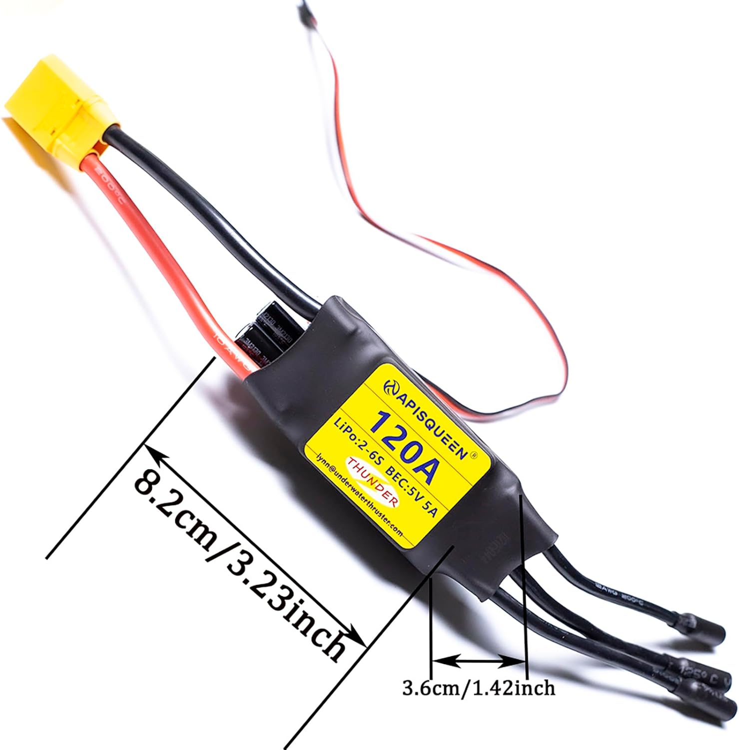
Image: The ApisQueen 120A ESC with its length (8.2cm / 3.23 inches) and width (3.6cm / 1.42 inches) clearly indicated.
5. Setup
Proper setup is crucial for the safe and correct operation of your ESC. Follow these steps carefully.
5.1 Connection Diagram
The following diagram illustrates the typical connection of the ESC to the battery, receiver, and motor. Note that the appearance of each model may vary, this is a typical model for reference only.

Image: A schematic diagram showing the connections between the battery, ESC, receiver, and motor. The battery connects to the ESC, the ESC connects to the motor, and the ESC's signal wire connects to the receiver.
5.2 Normal Start-up Procedure
- Turn on the transmitter. Move the throttle stick to the bottom (minimum) position.
- Connect the ESC to the battery. Wait for 2 seconds. The motor will emit a "BEEP" sound, indicating the number of LiPo cells detected.
- Wait for 1 second. The motor will emit a continuous long and 1 short "BEEP" sound, indicating that the brake is available. If it emits a long tone, the ESC is ready for operation.
5.3 Throttle Range Calibration
This procedure ensures your ESC recognizes the full throttle range of your transmitter.
- Turn on the transmitter. Move the throttle stick to the top (maximum) position.
- Connect the ESC to the battery. Wait for 2 seconds. The motor will emit a "BEEP-BEEP" sound, indicating that the full throttle position is memorized.
- Move the throttle stick to the bottom (minimum) position. Wait for 1 second. The motor will emit a "BEEP" sound, indicating that the low throttle position is memorized. The motor will then emit a "BEEP" sound, indicating the number of LiPo cells. If it emits a long tone, the ESC is ready for operation.
6. Operating Instructions
The ApisQueen 120A ESC allows for parameter programming directly via your remote control, eliminating the need for a separate programming card.
6.1 Programming Mode
To enter programming mode:
- Turn on the transmitter. Move the throttle stick to the top (maximum) position.
- Connect the ESC to the battery. Wait for 2 seconds. The motor will emit a "BEEP-BEEP" sound.
- Continue to wait for 5 seconds. The motor will emit a special tone "12321", indicating that it has entered programming mode.
Once in programming mode, you can use the throttle stick to navigate and select programming options. Refer to the detailed programming sequence provided with your product for specific parameter adjustments.
7. Maintenance
To ensure the longevity and optimal performance of your ApisQueen 120A ESC, follow these maintenance guidelines:
- Regular Inspection: Periodically check all wires and connectors for signs of wear, fraying, or corrosion. Ensure all solder joints are solid.
- Cleaning: Keep the ESC clean and free from dust, dirt, and debris. Use a soft, dry brush or compressed air for cleaning. Avoid using liquids.
- Storage: Store the ESC in a cool, dry place away from direct sunlight and extreme temperatures.
- Heat Management: Ensure adequate airflow around the ESC during operation to prevent overheating. Do not cover the ESC with insulating materials.
- Firmware Updates: Check the manufacturer's website for any available firmware updates, though this model is designed for parameter setting via remote control.
8. Troubleshooting
If you encounter issues with your ApisQueen 120A ESC, refer to the following common problems and solutions:
| Problem | Possible Cause | Solution |
|---|---|---|
| Motor does not start or stutters | Incorrect throttle calibration; poor motor/ESC connection; low battery voltage; motor/ESC damage. | Perform throttle range calibration. Check all connections. Ensure battery is charged and healthy. Inspect motor and ESC for damage. |
| ESC beeps continuously after power-up | Throttle stick not at minimum position; throttle signal loss; battery low voltage protection activated. | Ensure throttle stick is at minimum. Check receiver and transmitter connection. Charge or replace battery. |
| Motor runs in wrong direction | Incorrect motor wire connection. | Swap any two of the three motor wires connected to the ESC. |
| ESC overheats | Insufficient cooling; excessive load; incorrect propeller size. | Ensure adequate airflow. Reduce load or use a smaller propeller. Check for short circuits. |
| No response from ESC | No power to ESC; damaged ESC; incorrect BEC voltage. | Check battery connection. Verify BEC voltage setting is compatible with receiver. Contact support if ESC is unresponsive. |
9. Warranty and Support
ApisQueen products are manufactured to high-quality standards. For warranty information, technical support, or service inquiries, please contact your retailer or the ApisQueen customer service directly. Keep your purchase receipt as proof of purchase.
For further assistance, you may visit the official ApisQueen store or contact the seller through the platform where the product was purchased.

