1. Introduction
This user manual provides detailed instructions for the MicroZone MC6C 2.4G 6-channel remote control transmitter and receiver system. This system is designed for controlling various remote-controlled models, including fixed-wing airplanes, unmanned aerial vehicles (UAVs), ground vehicles, and ships. Please read this manual thoroughly before operating your MC6C system to ensure safe and correct usage.
2. Product Overview
The MicroZone MC6C is a 2.4GHz 6-channel radio control system featuring FSK modulation for reliable communication. It provides 6 PWM signal outputs and 1 SBUS signal output, offering versatility for various model types. The system includes a transmitter and a compatible receiver (e.g., MC7RB or MC6REmini).
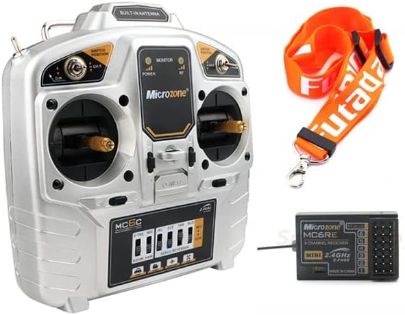
Figure 2.1: The MicroZone MC6C 2.4G 6-channel remote control transmitter and a compatible receiver, along with a neck strap.
Key Features:
- 2.4GHz FHSS (Frequency Hopping Spread Spectrum) technology for interference-free operation.
- 6 proportional channels for precise control.
- Supports 6 PWM signals and 1 SBUS signal output.
- Low voltage alarm with LED indicator and buzzer.
- Suitable for fixed-wing aircraft, UAVs, vehicles, and ships.
- Ground control range exceeding 800 meters.

Figure 2.2: Front view of the MicroZone MC6C transmitter, showing the gimbals, switches, and display panel.

Figure 2.3: Angled view of the MicroZone MC6C transmitter, highlighting the ergonomic design and control layout.
3. Specifications
| Parameter | Value |
|---|---|
| Model | MC6C |
| RF Range | 2401MHz - 2479MHz |
| RF Power | ≤ 100MW |
| Working Current | < 120MA |
| Working Voltage | 4.5V - 8.5V |
| Modulation Mode | FSK (Frequency Shift Keying) |
| Sensitivity | 1024 |
| Signal Output | 6 PWM signals, 1 SBUS signal |
| Ground Control Range | > 800m |
| Low Voltage Alarm | LED indicator and buzzer alarm |
| Power Supply | 6V (4 x 1.5V AA batteries) |
| Dimensions | 180mm x 185mm |
| Net Weight | 426g |
| Authentication Standards | FCC, CE_RED |
4. Setup
4.1 Battery Installation
- Locate the battery compartment on the back of the MC6C transmitter.
- Open the battery compartment cover.
- Insert four (4) 1.5V AA batteries, ensuring correct polarity (+/-) as indicated inside the compartment.
- Close the battery compartment cover securely.

Figure 4.1: Rear view of the MC6C transmitter with the battery compartment open, showing the slots for four AA batteries.
4.2 Binding the Receiver
The binding process establishes a secure communication link between the transmitter and the receiver. Refer to your receiver's specific manual for detailed binding instructions, as procedures may vary slightly. Generally, the steps involve:
- Ensure the transmitter is powered off.
- Connect power to the receiver. The receiver's LED indicator will typically flash, indicating it is in binding mode or awaiting a binding signal.
- While holding the bind button (if present) on the receiver, or following a specific power-on sequence, power on the transmitter.
- Observe the receiver's LED. A solid light usually indicates successful binding.
- Power off both the transmitter and receiver, then power them on again in the normal sequence (transmitter first, then receiver) to confirm the binding.
5. Operating Instructions
5.1 Powering On/Off
- To Power On: Ensure batteries are correctly installed. Flip the power switch on the transmitter to the "ON" position. The power indicator LED will illuminate. Then, power on your model's receiver.
- To Power Off: First, power off your model's receiver. Then, flip the power switch on the transmitter to the "OFF" position.
5.2 Basic Controls
The MC6C transmitter features two primary control sticks (gimbals) and several switches for controlling your model. The specific functions of each channel and switch depend on your model's configuration.

Figure 5.1: Detailed front view of the MC6C transmitter, showing the gimbals, trim levers, and various switches for channel control.
- Gimbals: Control primary functions like throttle, aileron, elevator, and rudder.
- Switches: Used for auxiliary functions such as landing gear, flaps, flight modes, or channel 5 and 6 control.
- Trims: Small levers near the gimbals used to fine-tune the neutral position of control surfaces.
5.3 Low Voltage Alarm
The MC6C transmitter is equipped with a low voltage alarm system. When the battery voltage drops below a safe operating level, the LED indicator will flash, and a buzzer will sound. This indicates that the batteries need to be replaced or recharged immediately to prevent loss of control.
6. Maintenance
- Cleaning: Use a soft, dry cloth to clean the transmitter. Avoid using solvents or abrasive cleaners.
- Storage: Store the transmitter in a cool, dry place away from direct sunlight and extreme temperatures. Remove batteries if storing for extended periods to prevent leakage.
- Inspection: Periodically check all switches, gimbals, and connections for any signs of wear or damage.
- Battery Care: Always use fresh, high-quality AA batteries. If using rechargeable batteries, ensure they are fully charged before each use.
7. Troubleshooting
| Problem | Possible Cause | Solution |
|---|---|---|
| Transmitter does not power on. | Dead or incorrectly installed batteries. | Check battery polarity and replace with fresh batteries. |
| No control response from model. | Receiver not bound, receiver not powered, or out of range. | Ensure receiver is powered and bound. Check range. |
| Low voltage alarm activates frequently. | Batteries are low or nearing end of life. | Replace batteries with new ones. |
| Intermittent control or signal loss. | Interference, transmitter/receiver too far apart, or damaged antenna. | Operate in an open area. Check antennas for damage. Re-bind if necessary. |
8. Safety Information
- Always operate your RC model in a safe and open area, away from people, animals, and property.
- Never operate your RC model near power lines, roads, or water bodies.
- Ensure the transmitter is powered on before the receiver, and powered off after the receiver, to prevent accidental activation.
- Regularly inspect your model and control system for any damage or loose connections.
- Do not operate the system if you are tired, under the influence of alcohol, or otherwise impaired.
- Keep the product out of reach of children when not in use.
9. Warranty and Support
For warranty information and technical support, please refer to the documentation provided with your purchase or contact the retailer where the product was acquired. Keep your proof of purchase for warranty claims.


