1. Introduction
This manual provides detailed instructions for the installation, operation, and maintenance of the PowMr 30A PWM Solar Charge Controller. This device is designed to manage the power flow from your solar panels to your battery bank, ensuring efficient charging and protecting your batteries from overcharge and over-discharge. It is compatible with 12V, 24V, 36V, and 48V systems and various battery types, including AGM, Gel, Flooded, and Lithium.
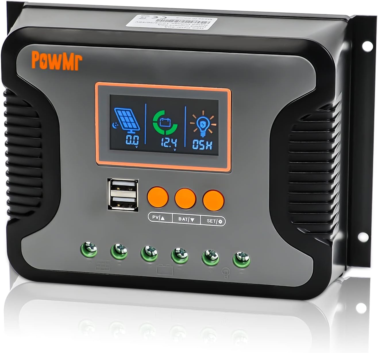
Figure 1: Front view of the PowMr 30A PWM Solar Charge Controller, showing the LCD display, USB ports, and control buttons.
2. Key Features
- Automatic System Voltage Detection: Automatically detects 12V, 24V, 36V, and 48V DC systems.
- Wide PV Input Voltage Range: Supports a maximum PV input voltage of 100V DC.
- Broad Battery Compatibility: Compatible with AGM, Gel, Flooded, LiFePO4, and Ternary Lithium batteries, with user-defined battery settings.
- 3-Stage PWM Charging: Utilizes Bulk, Boost, and Float charging stages for optimized battery health and longevity.
- Integrated Dual USB Ports: Provides 5V/2.5A (max) output for charging mobile devices.
- Backlit LCD Display: Real-time monitoring of charging current, generated energy, temperature, battery voltage, and error codes.
- Adjustable Load Enable Duration: Configurable solar light control and time control for load output.
- Comprehensive Protections: Includes protection against overheating, output short circuit, over-discharging, reverse polarity connection, and maximum charging current limits.
- Natural Convection Cooling: Fanless design for silent operation and efficient heat dissipation.

Figure 2: Overview of the multiple safety protections integrated into the controller.
3. Setup and Installation
Before installation, please read all safety instructions carefully. Ensure all connections are secure and correct to prevent damage to the controller or other components.
3.1 Safety Precautions
- Always connect the battery first, then the solar panel, and finally the load.
- Disconnect in the reverse order: load, then solar panel, then battery.
- Ensure proper ventilation around the controller.
- Install in a dry, cool environment, away from direct sunlight and moisture.
- Use appropriate circuit breakers and fuses for all connections.
3.2 Wiring Diagram
Follow the wiring sequence below to ensure safe and proper operation. Incorrect wiring may damage the controller.

Figure 3: Connection diagram for the PowMr Solar Charge Controller, showing connections for solar panels, battery, and load.
3.3 Connection Steps
- Connect the Battery: Connect the positive and negative terminals of the battery to the corresponding battery terminals on the controller. The controller will automatically detect the system voltage (12V/24V/36V/48V).
- Connect the Solar Panels: Connect the positive and negative terminals of the solar panels to the corresponding PV input terminals on the controller. Ensure the PV open circuit voltage does not exceed 100V DC.
- Connect the Load: Connect the positive and negative terminals of your DC load to the corresponding load terminals on the controller.
Important: Always connect the battery first and disconnect it last. This sequence prevents potential damage from voltage spikes.
4. Operating Instructions
The PowMr solar charge controller features an intuitive LCD display and three function keys for easy monitoring and parameter configuration.
4.1 LCD Screen Display and Buttons
The LCD screen provides real-time data and allows for parameter adjustments. The three buttons are: PV▲ (Up), BAT▼ (Down), and SET/Ⓞ (Set/Enter).

Figure 4: LCD screen display and button functions for navigation and settings.
Checking Information:
- Press "PV▲" to switch PV information (PV input voltage, PV input current, PV input power).
- Press "BAT▼" to switch battery information (current battery voltage, equipment temperature, battery calibration voltage, battery type, boost charging voltage, float charging voltage, low DC cut-off recovery voltage, low DC cut-off voltage).
4.2 Battery Type Selection
The controller supports various battery types. It is crucial to select the correct battery type for optimal charging and battery longevity.

Figure 5: Battery type compatibility and selection options.
To select the battery type:
- Press "BAT▼" until the battery type icon is displayed.
- Press and hold "SET/Ⓞ" to enter the setting mode.
- Use "PV▲" or "BAT▼" to cycle through the available battery types (e.g., SEL, USE, FLD, GEL, LiFePO4, Ternary Lithium, User-defined).
- Press "SET/Ⓞ" to confirm your selection.
4.3 Battery Voltage Calibration
For precise battery voltage readings, you can calibrate the controller's voltage measurement against a multimeter.

Figure 6: Battery voltage calibration process.
To calibrate:
- Navigate to the "battery calibration voltage" item using "BAT▼".
- Press and hold "BAT▼" to enter the calibration setting.
- Measure the actual battery voltage with a precise multimeter.
- Use "PV▲" or "BAT▼" to adjust the displayed voltage on the controller to match the multimeter reading.
- Press "SET/Ⓞ" to confirm and save the calibration.
4.4 3-Stage PWM Charging
The controller employs a 3-stage charging algorithm to optimize battery charging and extend battery life.

Figure 7: Explanation of the 3-stage PWM charging process.
- Bulk Charge: The battery is charged at maximum current until the voltage reaches the configured boost charging voltage.
- Boost Charge: The battery continues to charge at the configured boost charging voltage until it reaches a full charge state, with the charge current gradually decreasing.
- Float Charge: The controller reduces the battery voltage by lowering the charging current, maintaining the battery at a floating charging voltage to keep it fully charged.
4.5 Configure Load Enable Duration
The load output can be configured for continuous operation or controlled by solar light and time settings.
To configure load duration:
- Press and hold "SET/Ⓞ" to enter the load mode setting.
- Use "PV▲" or "BAT▼" to select the desired mode:
- -00H: Solar light control mode (load enabled when solar energy is sufficient).
- -24H: Turn on load immediately (default, continuous output).
- -01H-23H: Adjust the load enable duration (e.g., 01H for 1 hour, 23H for 23 hours).
- Press "SET/Ⓞ" to confirm your selection.
5. Maintenance
Regular maintenance ensures the longevity and optimal performance of your solar charge controller.
- Cleanliness: Keep the controller clean and free from dust and debris. Use a dry cloth for cleaning.
- Connections: Periodically check all wiring connections to ensure they are tight and free from corrosion. Loose connections can cause overheating and poor performance.
- Ventilation: Ensure the area around the controller is well-ventilated to allow for proper heat dissipation. Do not block the heat sink fins.
- Environmental Conditions: Verify that the operating environment remains within the specified temperature and humidity ranges.
- Battery Health: Monitor your battery's health and voltage regularly. Ensure the battery type setting on the controller matches your battery.
6. Troubleshooting
This section addresses common issues you might encounter with your solar charge controller.
| Problem | Possible Cause | Solution |
|---|---|---|
| Controller not turning on / No display | Battery not connected or low voltage; reverse polarity. | Check battery connections and voltage. Ensure correct polarity. Charge battery if voltage is too low. |
| Battery not charging | Solar panels not connected; insufficient sunlight; PV input voltage too low/high; incorrect battery type setting. | Check solar panel connections. Ensure adequate sunlight. Verify PV voltage is within range. Confirm correct battery type setting. |
| Load not working | Load disconnected; battery low voltage protection; load overcurrent/short circuit; load control setting. | Check load connections. Check battery voltage. Reduce load or clear short circuit. Adjust load enable duration setting. |
| Overheating | Poor ventilation; excessive load/charging current. | Ensure proper airflow around the controller. Reduce load or check for short circuits. |
| Inaccurate voltage reading | Calibration needed; loose battery connections. | Perform battery voltage calibration (refer to Section 4.3). Check and tighten battery connections. |
7. Specifications
Detailed technical specifications for the PowMr 30A PWM Solar Charge Controller.

Figure 8: Physical dimensions of the PowMr 30A PWM Solar Charge Controller.
| Parameter | Value |
|---|---|
| Model Number | 30A |
| System Voltage | 12V/24V/36V/48V Auto |
| Max PV Input Voltage | 100V DC |
| Max. Input Power (12V System) | 360W |
| Max. Input Power (24V System) | 720W |
| Max. Input Power (36V System) | 1080W |
| Max. Input Power (48V System) | 1440W |
| Charging Port Type | Dual USB (5V/2.5A max) |
| Product Dimensions | 7.36 x 3.7 x 1.93 inches |
| Item Weight | 1.12 pounds |
| Display Type | LCD |
| Manufacturer | PowMr |
8. Safety Information
The PowMr solar charge controller is equipped with multiple protection features to ensure safe operation of your solar power system.
- Reverse Polarity Connection Protection: Prevents damage if battery or solar panel connections are reversed.
- Over-Discharging Protection: Automatically disconnects the load when battery voltage drops below a safe level to prevent deep discharge.
- Overheating Protection: The controller will reduce charging current or shut down if its internal temperature exceeds safe limits.
- Output Short Circuit Protection: Protects the controller and load from damage in case of a short circuit on the load terminals.
- Maximum Charging Current Limitation: Limits the current to prevent overcharging the battery.
Always adhere to local electrical codes and safety standards during installation and operation. If you are unsure about any aspect of installation, consult a qualified electrician or solar professional.
9. Warranty and Support
For warranty information and technical support, please refer to the documentation included with your purchase or visit the official PowMr website. Keep your purchase receipt as proof of purchase for warranty claims.
No relevant product videos were found for this model.


