1. Introduction
Thank you for choosing the V-TAC VT-2432 RGB WIFI Controller. This manual provides essential information for the safe installation, operation, and maintenance of your device. Please read these instructions carefully before use and retain them for future reference.
2. Safety Information
- Ensure the power supply is disconnected before installation or maintenance.
- This device is designed for indoor use only.
- Do not expose the controller to moisture or extreme temperatures.
- Ensure the input voltage (DC12V-24V) matches the power supply for your LED strips. Exceeding the maximum output current (12A total, 6A per channel) can damage the device and connected lights.
- Consult a qualified electrician if you are unsure about any part of the installation.
3. Package Contents
- 1 x V-TAC VT-2432 RGB WIFI Controller
4. Product Overview
The V-TAC VT-2432 is an RGB WIFI Controller designed to manage V-TAC LED strips, allowing for color and brightness adjustments via a WIFI connection. It supports a wide range of input voltages and provides multiple output channels for RGB lighting.
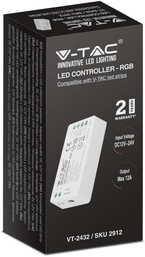
Figure 4.1: The V-TAC VT-2432 RGB WIFI Controller is packaged in a box displaying its brand, model number, and key features like 2-year warranty, input voltage, and maximum output current.
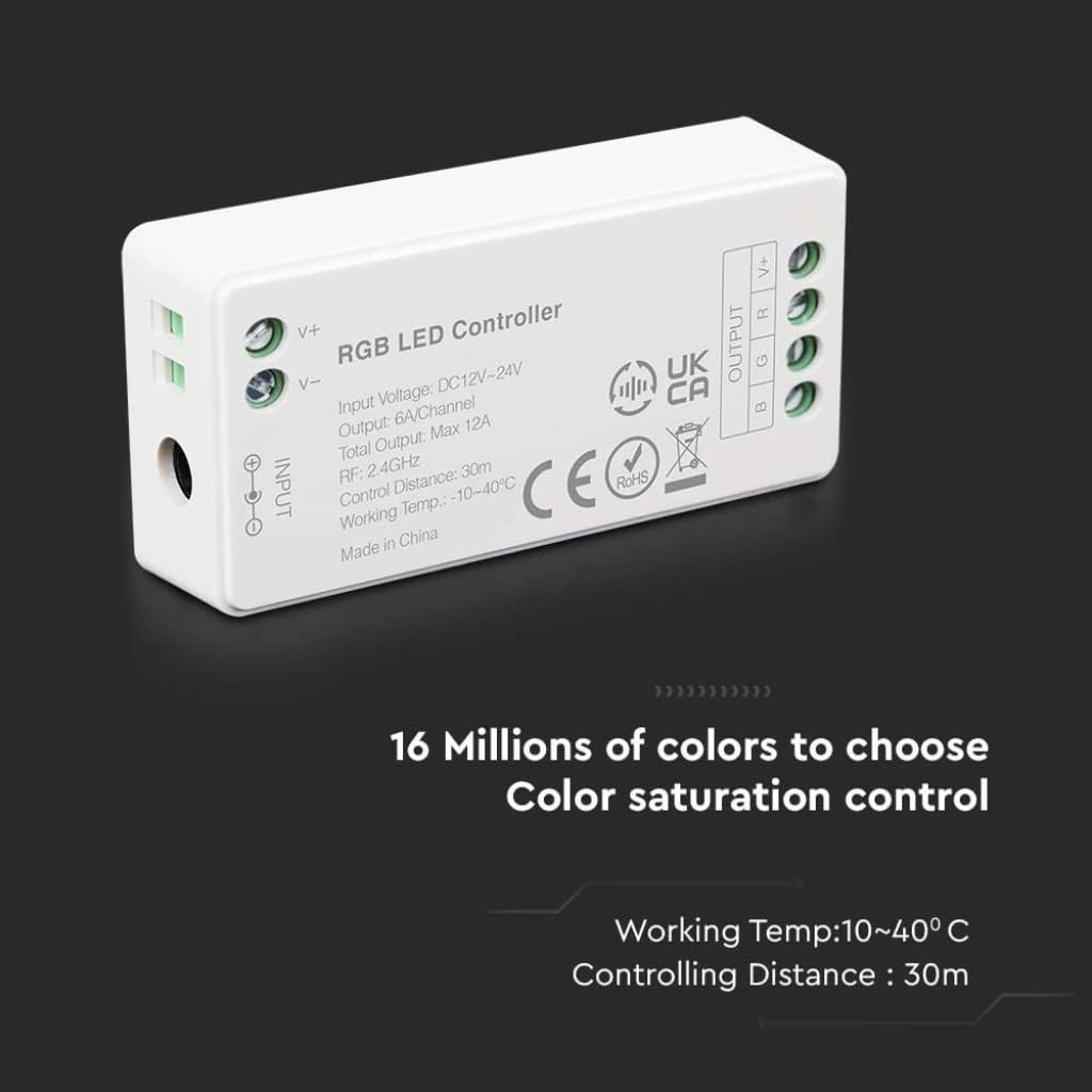
Figure 4.2: A detailed view of the V-TAC VT-2432 RGB LED Controller, highlighting its input (V+, V-) and output (V+, B, G, R) terminals. Key specifications such as input voltage (DC12V-24V), output (6A/Channel, Max 12A), RF frequency (2.4GHz), control distance (30m), and working temperature (10-40°C) are visible on the device casing.
5. Specifications
| Model Number | VT-2432 / 2912 |
| Input Voltage | DC12V-24V |
| Output Current | 6A per channel, Max 12A total |
| RF Frequency | 2.4GHz |
| Control Distance | Up to 30 meters |
| Working Temperature | 10°C to 40°C |
| Max Power | 100 Watts |
| Color Type | RGB |
| Manufacturer | V-TAC |
| Country of Origin | China |
| Warranty | 5 Years |
6. Setup
6.1 Wiring Connections
- Power Supply Connection: Connect the positive (+) and negative (-) terminals of your DC12V-24V power supply to the 'INPUT V+' and 'INPUT V-' terminals on the controller, respectively. Ensure correct polarity.
- LED Strip Connection: Connect the RGB LED strip to the 'OUTPUT' terminals. Match the V+ of the LED strip to the 'OUTPUT V+' terminal on the controller. Connect the Red (R), Green (G), and Blue (B) wires of the LED strip to the corresponding 'R', 'G', and 'B' terminals on the controller.
- Secure Connections: Ensure all wires are securely fastened in their terminals to prevent loose connections or short circuits.
6.2 WIFI Pairing (General Steps)
Specific pairing instructions may vary depending on the V-TAC smart home application. Generally, the process involves:
- Download the official V-TAC Smart Home app from your device's app store.
- Register or log in to your account.
- Power on the VT-2432 controller. The LED indicator on the controller may flash to indicate pairing mode.
- In the app, select 'Add Device' or a similar option.
- Follow the on-screen prompts to connect the controller to your 2.4GHz WIFI network.
7. Operating Instructions
Once successfully paired with the V-TAC Smart Home app, you can control your RGB LED strips using your smartphone or tablet.
- Color Selection: Use the color wheel or preset color options in the app to choose your desired light color.
- Brightness Adjustment: Adjust the brightness level using the slider control.
- Dynamic Modes: Select from various pre-programmed dynamic modes (e.g., flashing, fading, jumping) to create different lighting effects.
- Scheduling: Set timers or schedules for the lights to turn on/off or change modes automatically.
8. Maintenance
- Cleaning: Gently wipe the controller with a dry, soft cloth. Do not use harsh chemicals or abrasive cleaners.
- Storage: If storing the device for an extended period, disconnect it from the power supply and store it in a cool, dry place.
- Inspection: Periodically check all wiring connections to ensure they remain secure.
9. Troubleshooting
| Problem | Possible Cause | Solution |
|---|---|---|
| LED strip does not light up. | No power, incorrect wiring, faulty LED strip. | Check power supply connection. Verify wiring polarity. Test LED strip with another power source if possible. |
| Controller not connecting to WIFI. | Incorrect WIFI password, 5GHz network, controller too far from router. | Ensure correct 2.4GHz WIFI network and password. Move controller closer to the router. Reset controller and try pairing again. |
| Colors are incorrect or inconsistent. | Incorrect RGB wiring. | Verify that the R, G, B wires from the LED strip are connected to the correct R, G, B terminals on the controller. |
| Controller unresponsive. | Power issue, app malfunction. | Disconnect and reconnect power to the controller. Restart the V-TAC Smart Home app. |
10. Warranty
This V-TAC VT-2432 RGB WIFI Controller comes with a 5-year warranty from the date of purchase. This warranty covers manufacturing defects under normal use. It does not cover damage caused by improper installation, misuse, accidents, or unauthorized modifications. Please retain your proof of purchase for warranty claims.
11. Support
For further assistance, technical support, or warranty inquiries, please contact your local V-TAC distributor or visit the official V-TAC website for contact information.


