1. Introduction
This manual provides comprehensive instructions for the safe and effective use of the GEYA GRV8-01 DC12V Single Phase Voltage Monitoring Relay. This device is designed to monitor DC12V power supplies for overvoltage or undervoltage conditions, protecting connected equipment by disconnecting the circuit when voltage deviates from set thresholds. Please read this manual thoroughly before installation and operation.
2. Safety Information
- Installation and maintenance should only be performed by qualified personnel.
- Ensure the power supply is disconnected before performing any wiring or maintenance.
- Verify all connections are secure and correct according to the wiring diagram.
- Do not operate the device in environments exceeding its specified operating temperature or humidity ranges.
- This device is for voltage monitoring and protection; it is not a circuit breaker. Additional overcurrent protection may be required.
3. Product Overview
The GEYA GRV8-01 is a compact, single-phase voltage monitoring relay designed for DIN rail mounting. It features adjustable overvoltage (U>) or undervoltage (U<) thresholds, adjustable hysteresis (H), and an adjustable time delay (Tt). LED indicators provide visual feedback on the device's status.
- Controls its own supply voltage: Utilizes True RMS measurement for accurate monitoring.
- User-selectable operation mode: Choose between overvoltage or undervoltage protection via a knob.
- High accuracy: Voltage measurement accuracy is less than 1%.
- LED indicators: Green LED (Un) indicates supply voltage presence, Red LED (R) indicates relay status.
- Compact design: Ultra-small size (18mm width) for efficient space utilization on a 35mm DIN rail.

Figure 3.1: Front view of the GEYA GRV8-01 DC12V Voltage Monitoring Relay, showing the adjustment knobs and LED indicators.

Figure 3.2: Component overview of the GRV8-01, highlighting supply/monitoring terminals, LED indicators, function selection, voltage setting, hysteresis ratio, and adjustable time delay.
4. Specifications
The following table details the technical specifications for the GEYA GRV8-01 DC12V model.
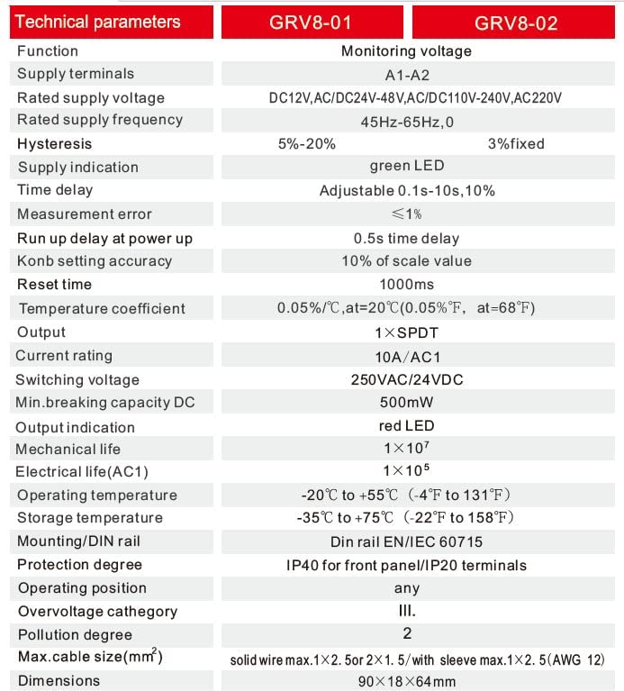
Figure 4.1: Detailed technical parameters for the GRV8-01 and GRV8-02 models.
| Parameter | Value (GRV8-01) |
|---|---|
| Function | Monitoring voltage (Over or Under Voltage) |
| Supply Terminals | A1-A2 |
| Rated Supply Voltage | DC12V |
| Rated Supply Frequency | 0 (DC) |
| Hysteresis | 5%-20% adjustable |
| Supply Indication | Green LED |
| Time Delay (Tt) | Adjustable 0.1s-10s, 10% |
| Measurement Error | <1% |
| Run Up Delay at Power Up | 0.5s time delay |
| Knob Setting Accuracy | 10% of scale value |
| Reset Time | 1000ms |
| Temperature Coefficient | 0.05%/°C, at=20°C (0.05%/°F, at=68°F) |
| Output | 1SPDT (Single Pole Double Throw) |
| Current Rating | 10A/AC1 |
| Switching Voltage | 250VAC/24VDC |
| Min. Breaking Capacity DC | 500mW |
| Output Indication | Red LED |
| Mechanical Life | 1 × 10⁷ |
| Electrical Life (AC1) | 1 × 10⁵ |
| Operating Temperature | -20°C to +55°C (-4°F to 131°F) |
| Storage Temperature | -35°C to +75°C (-22°F to 158°F) |
| Mounting/DIN Rail | DIN rail EN/IEC 60715 |
| Protection Degree | IP40 for front panel/IP20 terminals |
| Overvoltage Category | III |
| Pollution Degree | 2 |
| Max. Cable Size (mm²) | Solid wire max. 1x2.5 or 2x1.5 / with sleeve max. 1x2.5 (AWG 12) |
| Dimensions | 90 × 18 × 64 mm |
5. Installation
5.1 Mounting
The GRV8-01 is designed for easy installation on a standard 35mm DIN rail. Simply clip the device onto the DIN rail in your electrical enclosure.

Figure 5.1: Angled view of the GRV8-01, illustrating its compact size and suitability for DIN rail mounting.
5.2 Wiring
Connect the device according to the wiring diagram provided. Ensure all connections are tight and correctly terminated to prevent loose contacts and potential hazards.
- Supply/Monitoring Terminals (A1, A2): Connect the DC12V power supply to these terminals. The device monitors its own supply voltage.
- Output Contacts (11, 12, 14): The GRV8-01 features a 1SPDT (Single Pole Double Throw) relay output.
- Terminal 11: Common (COM)
- Terminal 12: Normally Closed (NC)
- Terminal 14: Normally Open (NO)

Figure 5.2: Wiring diagram for the GRV8-01, showing connections for supply (A1, A2) and relay output (11, 12, 14).

Figure 5.3: Top view of the GRV8-01, clearly indicating the A1(+), A2(-) supply terminals and the 11, 12, 14 output terminals.
6. Operation
The GRV8-01 features three adjustable knobs for setting the monitoring parameters: Function (U>/U<), Voltage Threshold (U), Hysteresis (H), and Time Delay (Tt).
6.1 Setting Parameters
Use a small screwdriver to carefully adjust the knobs to your desired settings.
- Function Knob (U>/U<): Selects whether the relay monitors for overvoltage (U>) or undervoltage (U<).
- Voltage Threshold Knob (U): Sets the specific voltage level at which the relay will trigger. For the DC12V model, this range is typically 9-15V.
- Hysteresis Knob (H): Adjusts the percentage difference between the trigger voltage and the reset voltage. This prevents rapid cycling of the relay when the voltage fluctuates near the threshold. The GRV8-01 has an adjustable hysteresis of 5%-20%.
- Time Delay Knob (Tt): Sets the delay (0.1s to 10s) before the relay activates or deactivates after a voltage event. This helps prevent nuisance tripping from momentary voltage fluctuations.

Figure 6.1: Visual guide for adjusting the function, voltage threshold, hysteresis, and time delay knobs on the GRV8-01.
6.2 Operating Modes
The GRV8-01 operates in either overvoltage or undervoltage mode, with non-locking or locking behavior depending on the specific application and settings.

Figure 6.2: Diagrams illustrating the operational behavior of the GRV8-01 in overvoltage (non-locking/locking) and undervoltage (non-locking/locking) modes.
7. Maintenance
The GEYA GRV8-01 is designed for reliable operation with minimal maintenance. Follow these guidelines to ensure longevity:
- Regularly inspect the device for any signs of physical damage or overheating.
- Ensure all terminal connections remain tight. Loose connections can lead to poor performance or damage.
- Keep the device clean and free from dust and debris. Use a dry, soft cloth for cleaning. Do not use liquid cleaners.
- Verify that the operating environment remains within the specified temperature and humidity ranges.
8. Troubleshooting
If you encounter issues with your GRV8-01 relay, consider the following common problems and solutions:
- Device not powering on (Green LED off):
Check the DC12V supply voltage to terminals A1 and A2. Ensure the voltage is within the operational range. Verify wiring connections. - Relay not activating/deactivating as expected:
- Review your set voltage threshold (U), hysteresis (H), and time delay (Tt) settings.
- Confirm the function knob (U>/U<) is set correctly for overvoltage or undervoltage monitoring.
- Measure the actual supply voltage to verify it crosses the set threshold.
- Check the load connected to the output contacts (11, 12, 14) for proper operation and current draw within the relay's rating.
- Relay cycling rapidly:
Increase the hysteresis (H) setting to provide a wider band between the trigger and reset points, or increase the time delay (Tt) to filter out momentary fluctuations. - Red LED (R) not indicating correctly:
The Red LED indicates the status of the output relay. If it does not correspond to the expected relay state based on voltage conditions and settings, re-check all parameters and wiring.
If problems persist after following these steps, contact GEYA customer support or a qualified electrician.
9. Warranty and Support
GEYA products are manufactured to high-quality standards. This product comes with a standard manufacturer's warranty against defects in materials and workmanship. For specific warranty terms, please refer to the documentation included with your purchase or visit the official GEYA website.
For technical support, product inquiries, or warranty claims, please contact GEYA customer service through their official channels. When contacting support, please have your product model (GRV8-01 DC12V) and purchase information readily available.


